Introduction
Motosize is an excellent tool to verify which robot or positioner will work with a tool, part, or fixture. However, it can feel intimidating for most people when trying to determine what data is needed to get the results needed.
Below are different Motosize scenarios and which data will be needed for each.
Robot: Estimated Tool Data
Estimated tool data is used when the tool design is still in a concept phase.
Data Needed:
- Estimated mass of the tool
- Estimated mass of the heaviest part
- Basic tool dimensions (Length, Width, and Height or Diameter and Height)
- Basic part dimensions (Length, Width, and Height or Diameter and Height)
- Estimated Center of Gravity (Cg) of the tool in X, Y, Z
- Estimated Center of Gravity (Cg) of the part in X, Y, Z
Note:
- Mass is in Kg and distance is in meters
- All dimensions start from the robot flange
- Results will report only on the B and T axis (5th & 6th axis)
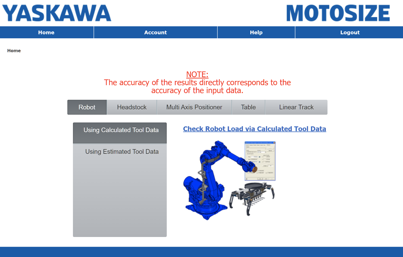
Robot: Calculated Tool Data
Calculated data is the most accurate method to size a robot. It relies on CAD data to generate mass, moment, and moment of inertia.
Important criteria before extracting mass data from the 3D CAD models:
- All components (at least the major components) need to be solid bodies (no surface bodies).
- All components need to have their mass defined (either by material type or overriding the default mass).
- If the robot is picking and moving a part, the part model needs to be included with the tool models.
- The origin of the tool/part assembly needs to be aligned as seen in the image above.
Data needed (based off the robot flange…see image above):
- Mass of tool or tool and heaviest part (kg)
- Center of gravity (Cg) (m)
- Moments of Inertia…note that if using Solidworks refer the M.O.I. values Lxx, Lyy, Lzz, Lxy, Lxz, Lyz instead of Ixx, etc. (kg-m^2).
Note: To save time from manually entering all the values, simply use the clipboard button to bulk-copy the mass properties to a blank text file. In Motosize use the “Import from CAD” button to auto-insert all the values.
Headstock
Data Needed:
- Mass of the Part and Fixture (kg)
- The Cycle Dwell Time (sec)
- The Load Inertia value about the headstock axis of rotation (kg-m^2)
- Best obtained from the 3D CAD assembly of the part/fixture
- Make sure to adjust the origin to be at the mating face of the headstock with an axis of choice perpendicular (normal) to the flange.
- The Cg off center value (R) (mm)
- If using just a Headstock and no tailstock…the overhang Cg of the part/fixture (D) (mm)
RM2 Positioners
Data Needed:
- Mass of the Part and Fixture (kg)
- The Load Inertia value about the headstock axis of rotation (kg-m^2)
- Best obtained from the 3D CAD assembly of the part/fixture.
- Make sure to adjust the origin to be at the mating face of the headstock with an axis of choice perpendicular (normal) to the flange.
- The tool axis dwell Time (sec)
- The Sweep axis dwell time (sec)
- Static Load weight imbalance (kg)
- Static Imbalance: Loading the tooling on an empty positioner…the difference in weight between side 'A' and side 'B' with no parts loaded into the tooling.
- Dynamic Load weight imbalance (kg)
- Dynamic imbalance: Loading the parts into the tooling, on the positioner…the difference in weight between side 'A' and side 'B' after parts are loaded into the tooling.
- The Cg off center value (R) (mm)
Tilt-Rotate Positioners
Data Needed:
- Mass of the Part and Fixture (kg)
- Cg of the part and fixture based off the flange (m)
- Moment of Inertia and Product of Inertia of the Part/fixture based off the flange (kg-m^2).
- Best obtained from a 3D CAD model…note that if using Solidworks refer the M.O.I. values Lxx, Lyy, Lzz, Lxy, Lxz, Lyz instead of Ixx, etc. (kg-m^2).
Rotating Table
Data Needed:
- Mass of the Part and Fixture (kg)
- The Load Inertia value about the table axis of rotation (kg-m^2)
- Best obtained from the 3D CAD assembly of the part/fixture
- Make sure to adjust the origin to be at the mating face of the table surface with an axis of choice perpendicular (normal) to the table surface.
- The Cycle Dwell Time (sec)
- The Cg distance (mm) (R) from the table axis of rotation.
Comments
0 comments
Please sign in to leave a comment.