Introduction:
It is always important to have the correct mass data for your End-Of-Arm Tool (EOAT) for sizing the correct robot model and using that tool data in the robot’s controller.
Below are step by step instructions to configure Solid Edge CAD data, export it to MotoSize, and calculate the results.
STEP 1: Check CAD model Integrity
In Solid Edge verify the following, in the Assembly:
- All relevant components are represented (anything that will generate enough mass.) This includes fasteners if they are numerous.
- Verify there are no duplicate components embedded in the assembly.
- All relevant models are solid bodies; not just surfaces (surfaces have no volume for mass to be calculated).
- All manufactured models have the correct material applied (steel, aluminum, plastics, rubber, etc.), giving it mass.
- All purchased components have either the correct material applied, or the mass is over-ridden with a value provided by the manufacturer.
- In addition to the tool mass, the mass of the part, being picked, needs to be represented, since it can significantly impact the overall mass properties. a. Select the largest, heaviest part that the tool will pick.
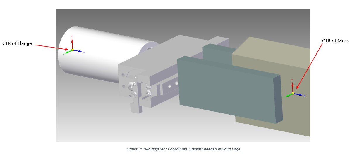
STEP 2: Setup two Coordinate Systems
It is critical that the two coordinate systems are accurately located. It will affect the center of gravity and moments of inertia.
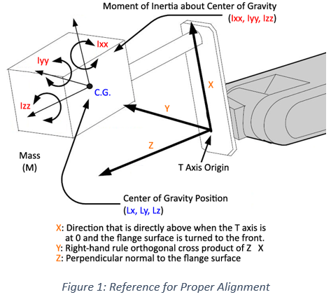
The first coordinate system needs to be located at the connection point of the robot flange and the tool…see Figure 1.
The second coordinate system needs to be located at the center of mass with its XYZ orientation matching Figure 1
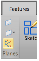
- In the Solid Edge Features Tab Select Coordinate System and choose to key data or use geometry to define it.
- Use the Ribbon bar to define the location and orientation of each coordinate system.

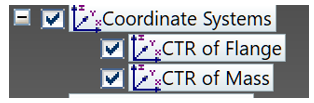
- In the Pathfinder, rename the coordinate systems to CTR of Flange and CTR of Mass.
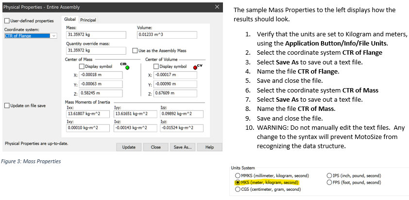
STEP 3: Configure and Output the Mass Data
After the models and origin have been configured, the next step is the mass properties output.
It can be found in the Inspect Tab, MV Properties 
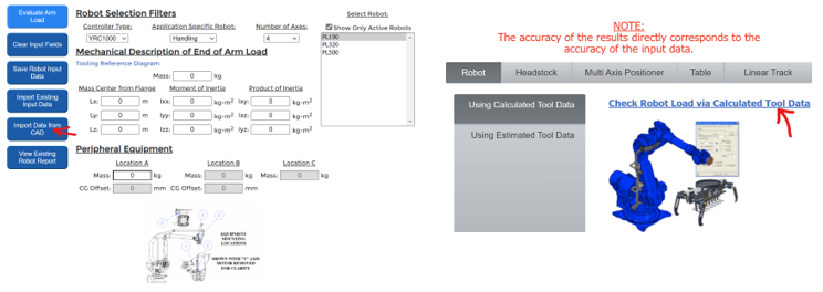
STEP 4: Enter the Data in MotoSize
Login to MotoSize.motoman.com
At the main page select the option for CHECK ROBOT VIA CALCULATED DATA
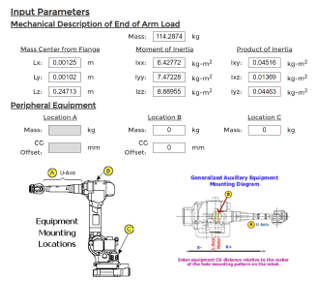
At the Data Input Screen:
- Select the button Import Data From CAD
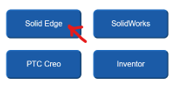
- Select Solid Edge
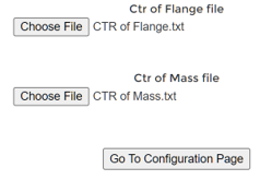
- Browse for the recently created text files and load based off the image below. Select Go to Configuration Page.
- Back on the Data Entry Screen the mass, center of mass, and moments of Inertia will be filled in.
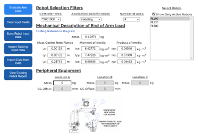
- Selection of the robot model can be assisted by using the Controller, Application, and Axes filters.
- If any Peripheral equipment will be mounted to the robot, enter the data in the available fields. The drawing at the bottom of the screen can assist.
- Once all data is filled in, select the Evaluate Arm Load button.
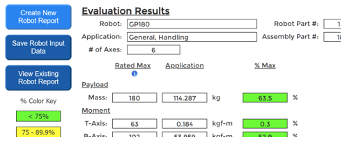
STEP 5: Review the Results
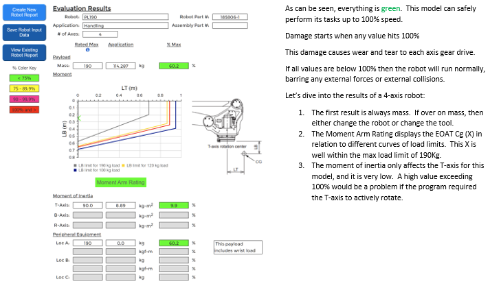
If a 4-axis arm was selected
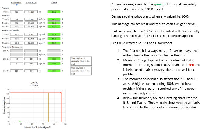
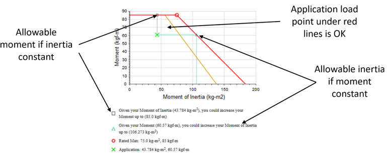
If a 6-axis arm was selected
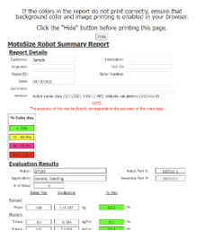
At the bottom of the results are the Input values.
Assuming the tool is a completed design, these values can be programmed into the actual robot controller’s tool data.
It is more accurate than using hand calculations or letting the controller estimate the tool data.
STEP 6: Saving the Results
Once satisfied with the results, they can be saved to a PDF, or the results can be saved as an XML file.
Most people, though, prefer the PDF.
- Select Create New Robot Report
- Fill in the Customer field and any other optional field desired
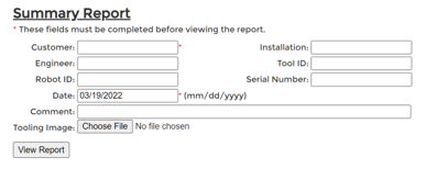
- A useful option is to include an image of the actual tool. Just select the Tooling Image button and choose any image file.
- When ready, select View Report
- The finished report will appear…just select Printer Friendly Page
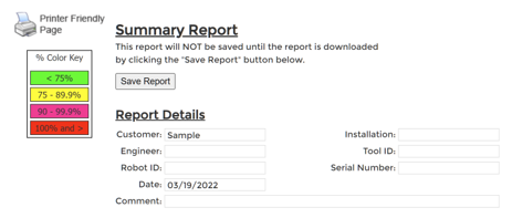
- The printer friendly page will display message reminding the user to verify their browser background graphics are checked in the printer settings. a. If not, then the color key will be gray only and harder to interpret.
- Select the Hide button to remove the message,
- Use the browser to print to PDF (built-in to Chrome and Edge browsers)
- Done
Comments
0 comments
Please sign in to leave a comment.