| S-Axis Grease Replenishment |
|
|
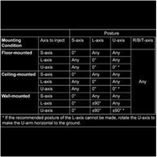
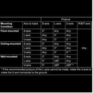
1. Orient the S-Axis according to the posture chart that can be found in the manipulator manual.
WARNING: Use of non-specified grease will void your warranty.
CAUTION: If using a pneumatic grease pump, set the air supply pressure to 0.3MPa or less and the injection rate at 7g/s or less.
NOTE: For ceiling-mounted robots, the outlet port and the grease inlet are inverted (the lower one is the inlet).
|
 |
| 2. For floor mounted robot, orient the S-Axis such that it is at home position (0 degrees). |
 |
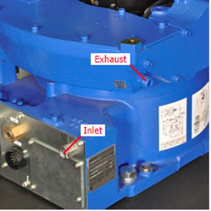
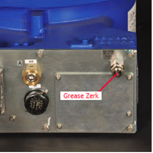
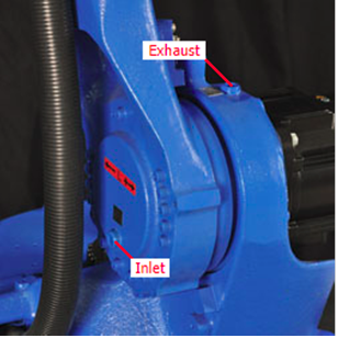
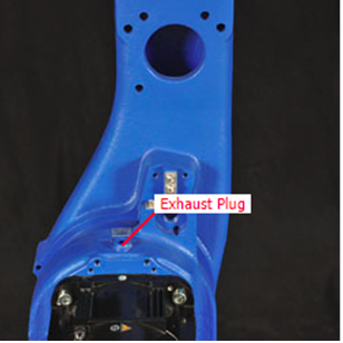
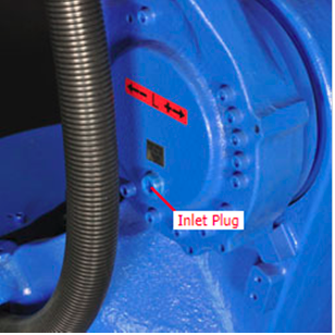
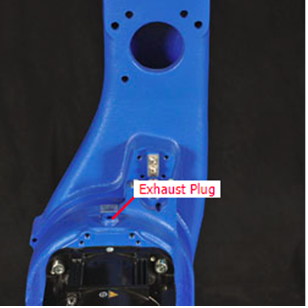
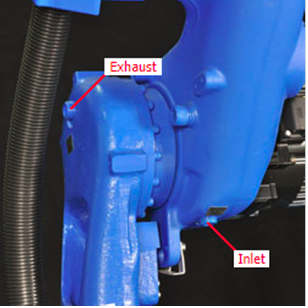
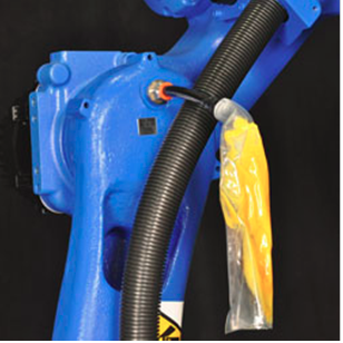
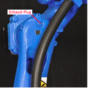
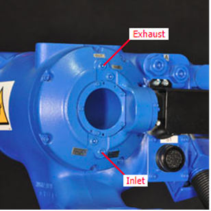
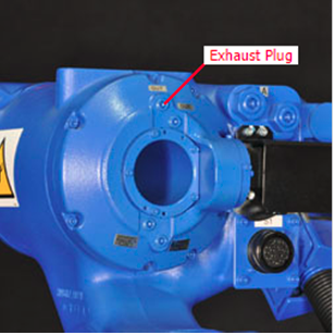
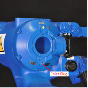
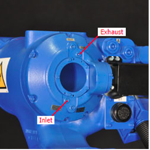
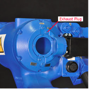
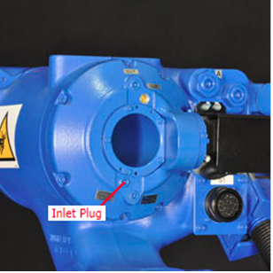
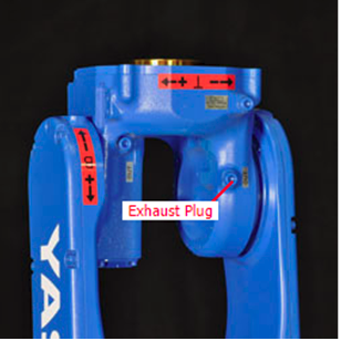
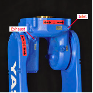
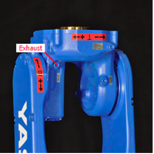
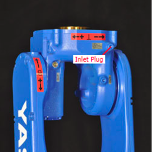
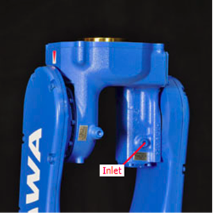
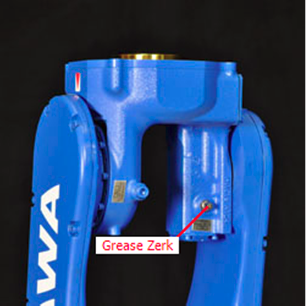
| 3. Locate the inlet, on the base plate, and exhaust, on the right side of the robots base just below where the wire harness enters the robot base. |
 |
|
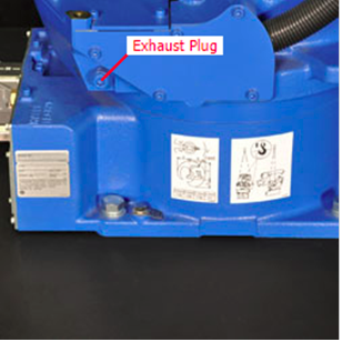
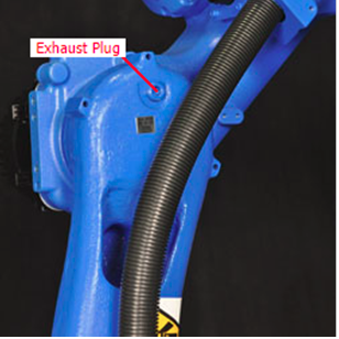
4. Remove the exhaust plug.
NOTE: If grease is injected without removing the exhaust plug, grease may leak inside the motor and/or damage the oil seal.
|
 |
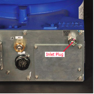
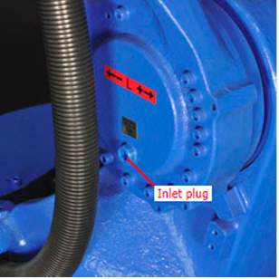
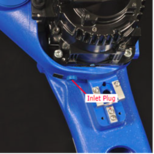
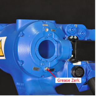
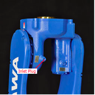
| 5. Remove the inlet plug. |
 |
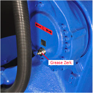
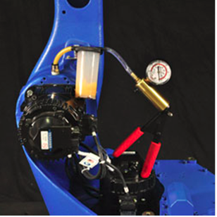
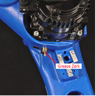
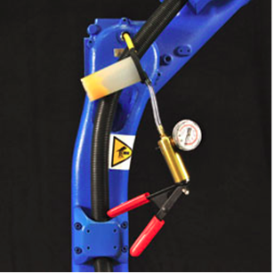
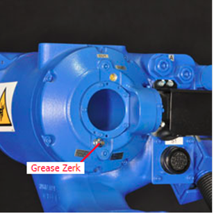
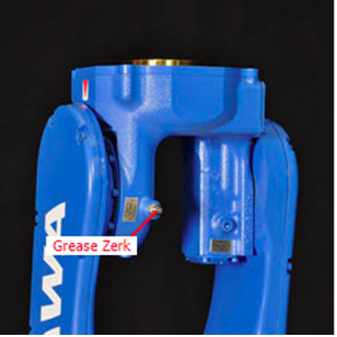
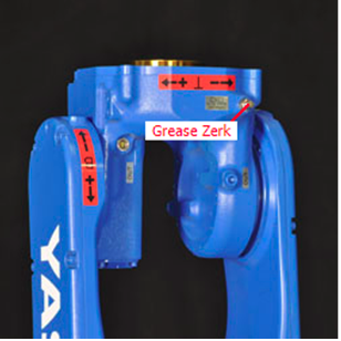
| 6. Install A-PT3/8 grease zerk into the inlet and inject Molywhite RE No.00 grease. Inject approximately 700g or 840cc of grease. Stop injecting grease when a mixture of old grease and new grease in an equal ratio can be seen coming from the exhaust port. |
 |
| 7. Remove A-PT3/8 grease zerk from the inlet. |
 |
| 8. Wipe off excess grease from inlet port. Clean the inlet plug. Wrap seal tape, such as Three Bond TB4501, around the threads of the plug and reinstall in the inlet port. Torque (1.7 kg-m) the inlet plug. |
|
|
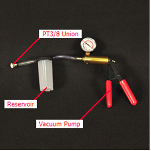
9. Assemble a grease discharge unit. The components used are:
• PT3/8 Union
• Vacuum Pump
• Reservoir
• Tubing*
* Tubing length must be 150mm or less and inside diameter must be 6mm or greater.
|
 |
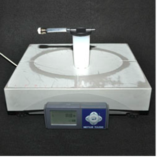
| 10. Weigh the empty grease reservoir and make note of its weight. |
 |
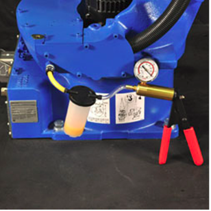
| 11. Install the grease discharge unit into the exhaust port of the S-Axis. Discharge grease by suctioning grease out of the exhaust port. Make sure to keep suction pressure at 0.025MPa or less. Stop suctioning when either the vacuum breaks or the desired amount of grease has been extracted. The amount of discharged grease for the S-Axis should be 25g (+/-5g) or 30cc (+/-5cc). Remove the grease discharge unit from the exhaust port. |
 |
| 12. Weigh the grease reservoir and calculate the amount of grease extracted by subtracting the empty reservoir weight obtained earlier. |
|
| 13. If the amount of grease discharged from the S-Axis does not equal 25g (+/-5g) or 30cc (+/-5cc), operate the S-Axis again in teach mode, moving the S-Axis from -45 degrees to +45 degrees about 5 times. |
|
|
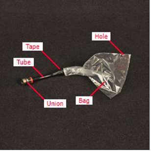
14. Assemble a grease receiving unit. The components used are:
• PT3/8 Union (inside dia. of at least 6mm)
• Tubing (inside dia. of at least 6mm)
• Plastic Bag
• Tape
Insert the tubing (approx. 4" in length) into the union. Place the bag over the opposite end of the tubing and use tape to secure bag to tubing. Make a small cut or puncture in the bag and mark its location so that it can be easily found.
|
 |
|
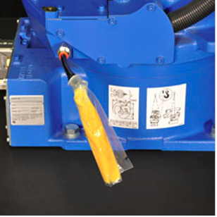
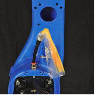
15. Install the grease receiving unit into the exhaust port of the S-Axis.
Perform a playback operation for 15 minutes. Teach points so that the S-Axis operates form -45 degrees to +45 degrees with a 1 second timer at each change of direction. Speed should be no greater than VJ=50.00. During this time, grease may be discharged.
|
 |
| 16. Remove the grease receiving unit from the exhaust port. Wipe off excess grease from exhaust port. Clean the exhaust plug. Wrap seal tape, such as Three Bond TB4501, around the threads of the plug and reinstall in the exhaust port. Torque (1.7 kg-m) the exhaust plug. |
|
| L-Axis Grease Replenishment |
|
1. Orient the L-Axis according to the posture chart that can be found in the manipulator manual.
WARNING: Use of non-specified grease will void your warranty.
CAUTION: If using a pneumatic grease pump, set the air supply pressure to 0.3MPa or less and the injection rate at 7g/s or less.
NOTE: For ceiling-mounted robots, the outlet port and the grease inlet are inverted (the lower one is the inlet). |
 |
| 2. For floor mounted robot, orient the L-Axis such that it is at home position (0 degrees). |
|
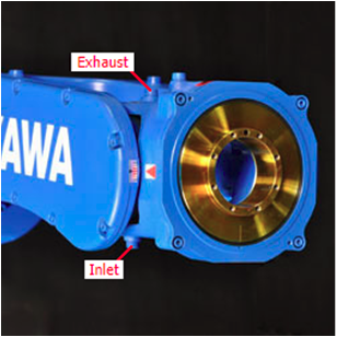
| 3. Locate the exhaust and inlet plugs. |
 |
4. Remove the exhaust plug.
NOTE: If grease is injected without removing the exhaust plug, grease may leak inside the motor and/or damage the oil seal. |
 |
| 5. Remove the inlet plug. |
 |
| 6. Install A-PT3/8 grease zerk into the inlet and inject Molywhite RE No.00 grease. Inject approximately 450g or 540cc of grease. Stop injecting grease when a mixture of old grease and new grease (distinguished by color) can be seen coming from the exhaust port in an equal ratio. |
 |
| 7. Remove A-PT3/8 grease zerk from the inlet. |
|
| 8. Wipe off excess grease from inlet port. Clean the inlet plug. Wrap seal tape, such as Three Bond TB4501, around the threads of the plug and reinstall in the inlet port. Torque (1.7 kg-m) the inlet plug. |
 |
9. Assemble a grease discharge unit. The components used are:
• PT3/8 Union
• Vacuum Pump
• Reservoir
• Tubing*
* Tubing length must be 150mm or less and inside diameter must be 6mm or greater. |
|
| 10. Weigh the empty grease reservoir and make note of its weight. |
|
| 11. Install the grease discharge unit into the exhaust port of the L-Axis. Discharge grease by suctioning grease out of the exhaust port. Make sure to keep suction pressure at 0.025MPa or less. Stop suctioning when either the vacuum breaks or the desired amount of grease has been extracted. The amount of discharged grease for the L-Axis should be 50g (+/-5g) or 60cc (+/-10cc). Remove the grease discharge unit from the exhaust port. |
 |
| 12. Weigh the grease reservoir and calculate the amount of grease extracted by subtracting the empty reservoir weight obtained earlier. |
|
| 13. If the amount of grease discharged from the L-Axis does not equal 50g (+/-5g) or 60cc (+/-10cc), operate the L-Axis again in teach mode, moving the L-Axis from -45 degrees to +45 degrees about 5 times. |
|
14. Assemble a grease receiving unit. The components used are:
• PT3/8 Union (inside dia. of at least 6mm)
• Tubing (inside dia. of at least 6mm)
• Plastic Bag
• Tape
Insert the tubing (approx. 4" in length) into the union. Place the bag over the opposite end of the tubing and use tape to secure bag to tubing. Make a small cut or puncture in the bag and mark its location so that it can be easily found. |
|
15. Install the grease receiving unit into the exhaust port of the L-Axis.
Perform a playback operation for 15 minutes. Teach points so that the L-Axis operates form -45 degrees to +45 degrees with a 1 second timer at each change of direction. Speed should be no greater than VJ=50.00. During this time, grease may be discharged. |
 |
| 16. Remove the grease receiving unit from the exhaust port. Wipe off excess grease from exhaust port. Clean the exhaust plug. Wrap seal tape, such as Three Bond TB4501, around the threads of the plug and reinstall in the exhaust port. Torque (1.7 kg-m) the exhaust plug. |
 |
| U-Axis Grease Replenishment |
|
1. Orient the U-Axis according to the posture chart that can be found in the manipulator manual.
WARNING: Use of non-specified grease will void your warranty.
CAUTION: If using a pneumatic grease pump, set the air supply pressure to 0.3MPa or less and the injection rate at 7g/s or less.
NOTE: For ceiling-mounted robots, the outlet port and the grease inlet are inverted (the lower one is the inlet). |
 |
| 2. For floor mounted robot, orient the U-Axis such that it is at home position (0 degrees) with the U-arm horizontal with the ground. |
|
| 3. Locate the exhaust and inlet plugs. |
 |
4. Remove the exhaust plug.
NOTE: If grease is injected without removing the exhaust plug, grease may leak inside the motor and/or damage the oil seal. |
 |
| 5. Remove the inlet plug. |
 |
| 6. Install A-PT3/8 grease zerk into the inlet and inject Molywhite RE No.00 grease. Inject approximately 350g or 420cc of grease. Stop injecting grease when a mixture of old grease and new grease (distinguished by color) can be seen coming from the exhaust port in an equal ratio. |
|
| 7. Remove A-PT3/8 grease zerk from the inlet. |
 |
| 8. Wipe off excess grease from inlet port. Clean the inlet plug. Wrap seal tape, such as Three Bond TB4501, around the threads of the plug and reinstall in the inlet port. Torque (1.7 kg-m) the inlet plug. |
|
9. Assemble a grease discharge unit. The components used are:
• PT3/8 Union
• Vacuum Pump
• Reservoir
• Tubing*
* Tubing length must be 150mm or less and inside diameter must be 6mm or greater. |
|
| 10. Weigh the empty grease reservoir and make note of its weight. |
|
| 11. Install the grease discharge unit into the exhaust port of the U-Axis. Discharge grease by suctioning grease out of the exhaust port. Make sure to keep suction pressure at 0.025MPa or less. Stop suctioning when either the vacuum breaks or the desired amount of grease has been extracted. The amount of discharged grease for the U-Axis should be 40g (+/-5g) or 45cc (+/-10cc). Remove the grease discharge unit from the exhaust port. |
 |
| 12. Weigh the grease reservoir and calculate the amount of grease extracted by subtracting the empty reservoir weight obtained earlier. |
|
| 13. If the amount of grease discharged from the U-Axis does not equal 40g (+/-5g) or 45cc (+/-10cc), operate the U-Axis again in teach mode, moving the U-Axis from -45 degrees to +45 degrees about 5 times. |
|
14. Assemble a grease receiving unit. The components used are:
• PT3/8 Union (inside dia. of at least 6mm)
• Tubing (inside dia. of at least 6mm)
• Plastic Bag
• Tape
Insert the tubing (approx. 4" in length) into the union. Place the bag over the opposite end of the tubing and use tape to secure bag to tubing. Make a small cut or puncture in the bag and mark its location so that it can be easily found. |
|
15. Install the grease receiving unit into the exhaust port of the U-Axis.
Perform a playback operation for 15 minutes. Teach points so that the U-Axis operates form -45 degrees to +45 degrees with a 1 second timer at each change of direction. Speed should be no greater than VJ=50.00. During this time, grease may be discharged. |
 |
| 16. Remove the grease receiving unit from the exhaust port. Wipe off excess grease from exhaust port. Clean the exhaust plug. Wrap seal tape, such as Three Bond TB4501, around the threads of the plug and reinstall in the exhaust port. Torque (1.7 kg-m) the exhaust plug. |
 |
|
R-Axis Grease Replenishment
|
|
1. Orient the U-arm horizontal with the ground by lining up the alignment arrows for the U-Axis.
WARNING: Use of non-specified grease will void your warranty.
CAUTION: If using a pneumatic grease pump, set the air supply pressure to 0.3MPa or less and the injection rate at 7g/s or less. |
|
| 2. Locate the exhaust and inlet plugs. |
 |
| 3. Remove the exhaust plug. |
 |
| 4. Remove the inlet plug. |
 |
5. Install A-PT1/8 grease zerk into the inlet. Inject approximately 7g or 8cc of Harmonic SK-1A grease for periodic maintenance.
CAUTION: The exhaust port is for AIR exhaust only. The grease is not exhausted from the exhaust port. Do not inject excessive grease into the inlet. |
 |
| 6. Remove A-PT1/8 grease zerk from the inlet. |
|
| 7. Wipe off excess grease from inlet port. Clean the inlet plug. Wrap seal tape, such as Three Bond TB4501, around the threads of the plug and reinstall in the inlet port. Torque (0.49 kg-m) the inlet plug. |
 |
| 8. Clean any debris from exhaust port. Clean the exhaust plug. Wrap seal tape, such as Three Bond TB4501, around the threads of the plug and reinstall in the exhaust port. Torque (0.49 kg-m) the exhaust plug. |
 |
|
R-Axis Gear Grease Replenishment
|
|
1. Orient the U-arm horizontal with the ground by lining up the alignment arrows for the U-Axis.
WARNING: Use of non-specified grease will void your warranty.
CAUTION: If using a pneumatic grease pump, set the air supply pressure to 0.3MPa or less and the injection rate at 7g/s or less.
NOTE: For ceiling-mounted robots, the outlet port and the grease inlet are inverted (the lower one is the inlet). |
|
| 2. Locate the exhaust and inlet plugs. |
 |
| 3. Remove the exhaust plug. |
 |
| 4. Remove the inlet plug. |
 |
5. Install A-PT1/8 grease zerk into the inlet. Inject approximately 3g or 4cc of Harmonic SK-1A grease.
CAUTION: The exhaust port is for AIR exhaust only. The grease is not exhausted from the exhaust port. Do not inject excessive grease into the inlet. |
 |
| 6. Remove A-PT1/8 grease zerk from the inlet. |
 |
| 7. Wipe off excess grease from inlet port. Clean the inlet plug. Wrap seal tape, such as Three Bond TB4501, around the threads of the plug and reinstall in the inlet port. Torque (0.49 kg-m) the inlet plug. |
 |
| 8. Clean any debris from exhaust port. Clean the exhaust plug. Wrap seal tape, such as Three Bond TB4501, around the threads of the plug and reinstall in the exhaust port. Torque (0.49 kg-m) the exhaust plug. |
 |
| B-Axis Grease Replenishment |
|
1. Orient the U-arm horizontal with the ground by lining up the alignment arrows for the U-Axis and position the wrist with the B-Axis straight out as shown.
WARNING: Use of non-specified grease will void your warranty.
CAUTION: If using a pneumatic grease pump, set the air supply pressure to 0.3MPa or less and the injection rate at 7g/s or less. |
|
| 2. Locate the exhaust and inlet plugs on the wrist. |
 |
| 3. Remove the M6 socket head cap screw exhaust plug for the B-Axis drive. |
 |
| 4. Remove the M6 socket head cap screw inlet plug. |
 |
5. Install A-MT6X1 grease zerk into the inlet. Inject approximately 7g or 8cc of Harmonic SK-1A grease for periodic maintenance.
CAUTION: The exhaust port is for AIR exhaust only. The grease is not exhausted from the exhaust port. Do not inject excessive grease into the inlet. |
 |
| 6. Remove A-MT6X1 grease zerk from the inlet. |
|
| 7. Wipe off excess grease from inlet. Apply solventless silicone compound such as Three Bond 1206C to the threads of the M6 socket head cap screw inlet plug and replace with torque (0.6 kg-m). |
 |
| 8. Clean any debris from exhaust port. Apply solventless silicone compound such as Three Bond 1206C to the threads of the M6 socket head cap screw exhaust plug and replace with torque (0.6 kg-m). |
 |
| T-Axis Gear Grease Replenishment |
|
1. Orient the U-arm horizontal with the ground by lining up the alignment arrows for the U-Axis and position the wrist with the B-Axis straight out as shown.
WARNING: Use of non-specified grease will void your warranty.
CAUTION: If using a pneumatic grease pump, set the air supply pressure to 0.3MPa or less and the injection rate at 7g/s or less. |
|
| 2. Locate the exhaust and inlet plugs on the top of the wrist. |
 |
| 3. Remove the M6 socket head cap screw exhaust plug. |
 |
| 4. Remove the M6 socket head cap screw inlet plug. |
 |
5. Install A-MT6X1 grease zerk into the inlet. Inject approximately 2g or 2cc of Harmonic SK-1A grease for periodic maintenance.
CAUTION: The exhaust port is for AIR exhaust only. The grease is not exhausted from the exhaust port. Do not inject excessive grease into the inlet. |
 |
| 6. Remove A-MT6X1 grease zerk from the inlet. |
 |
| 7. Wipe off excess grease from inlet. Apply solventless silicone compound such as Three Bond 1206C to the threads of the M6 socket head cap screw inlet plug and replace with torque (0.6 kg-m). |
|
| 8. On the bottom of the wrist, locate and remove the second inlet plug. |
 |
9. Install A-MT6X1 grease zerk into the inlet. Inject approximately 2g or 2cc of Harmonic SK-1A grease for periodic maintenance.
CAUTION: The exhaust port (which was removed in step 2) is for AIR exhaust only. The grease is not exhausted from the exhaust port. Do not inject excessive grease into the inlet. |
 |
| 10. Remove A-MT6X1 grease zerk from the inlet. |
|
| 11. Wipe off excess grease from inlet. Apply solventless silicone compound such as Three Bond 1206C to the threads of the M6 socket head cap screw inlet plug and replace with torque (0.6 kg-m). |
 |
| 12. On the top of the wrist, clean any debris from exhaust port. Apply solventless silicone compound such as Three Bond 1206C to the threads of the M6 socket head cap screw exhaust plug and replace with torque (0.6 kg-m). |
 |
Comments
0 comments
Please sign in to leave a comment.