Scope and Purpose
This document provides a starting point for setting up MotoSight2D with Conveyor Tracking. Depending on your application setup and configuration, MotoPick software may be better suited for your needs.
Refer to manuals below for more in-depth information. It is recommended that you review the MotoSight 2D manual and Conveyor tracking manual, specific to your controller before proceeding. Manuals are available at https://www.motoman.com/en-us/service-training/product-documentation
- 169004-1CD MotoSight 2D
- 161365-1CD FS100 Conveyor Synchronized Function
- 157800-1CD DX100 Conveyor Synchronized Function
- 165637-1CD DX200 Conveyor Synchronized Function
- 179327-1CD YRC1000 Conveyor Synchronized Function
- 185021-1CD YRC1000micro Conveyor Synchronized Function
Overview:
-
-
- Hardware requirements
1.1 Cognex PC Version
1.2 Cognex Camera Version - Creating a Tool File
2.1 Setting X, Y, Z of Tool Center Point (TCP) with calibration function
2.2 Setting Weight, Center of Mass, Gravity with gravity measurement function
2.3 Setting Inertia for End of Arm Tooling (EOAT) - Conveyor Calibration User Frame(UF)
3.1 Creating a User Frame relative to the conveyor
3.2 Where to assign user frame in conveyor file - Navigating Conveyor Menus on Teach Pendant
4.1 Conveyor Condition file
4.2 Conveyor Monitor file
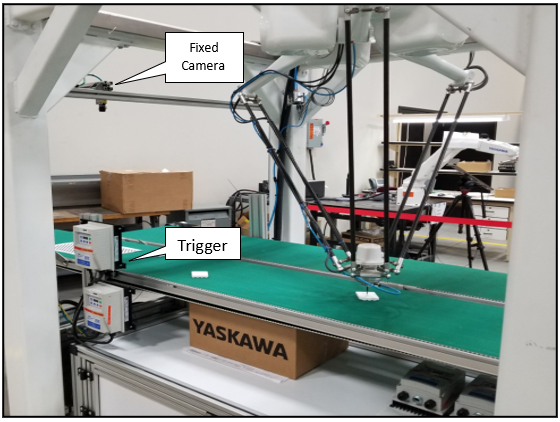
4.3 Wiring and verifying limit switch (trigger) for conveyor - Calculating position resolution
5.1 Explanation of position resolution
5.2 Preparing part for position resolution
5.3 Measuring distance traveled to get value L.
5.4 How to calculate the data with formula
5.5 Verifying and adjusting conveyor position resolution
5.6 Conveyor tracking instruction tags- Verify Proper MS2D Setup
6.1 MS2D heartbeat
6.2 Valid MotoPlus license - Setting IP address of devices and controller
7.1 Where to locate IP addresses of the camera
7.2 Default values from Yaskawa on all devices - Cognex setup and version upgrade
8.1-8.18 Connecting to a camera
8.19-8.21 Upgrading software on the camera
8.22-8.25 Loading camera jobs already installed in camera - Camera setup and calibration
9.1 MotoSight 2D video setup overview
9.2-9.4 Printing the calibration grid and parameter windows
9.5-9.9 Calibrating the grid in relation to the camera- User frame with robot to grid
10.1-10.3 Setting up user frame in relation to the camera
10.4. Job structure. Relative job versus Position Variables
10.5-10.6 Capturing CTP data with a relative job.
- Setting up MotoSight 2D pendant app.
11.1-11.2 Launching MS2D app and setting IP address
11.3-11.8 Troubleshooting steps if camera is not communicating to the controller
11.9-11.11 Assigning results
11.12 Verifying results
- Hardware requirements
-
Section 1: Hardware Requirements
1.1. Hardware Requirements (Laptop)
Laptop with Cognex Insight Explorer Version 4.9.x or greater loaded (If you don’t have version 4.9.x it can be downloaded from http://www.cognex.com/Support/InSight/Software.aspx)
1.2. Cognex version requirements
If the camera firmware version is lower than 4.05, you will need to upgrade the camera firmware. Do not upgrade the camera firmware higher than the 4.10.3 (Using Insight Explorer version 5.3.0).
If the camera firmware version is higher than 5.7.3, you will need to downgrade the camera. Do not downgrade the camera firmware lower than 4.10.3 (Using Insight Explorer version 5.3.0).
5.5 Is the official supported firmware. If you have issues with a non-official, please flash 5.5
Section 2: Creating a good TCP
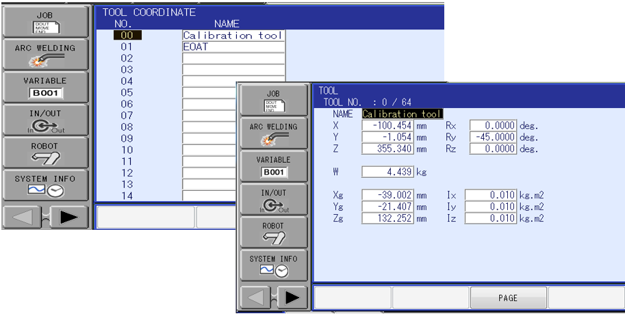
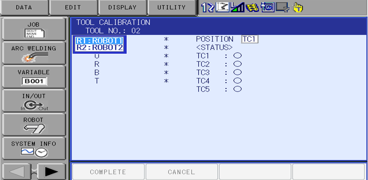
2.1. Select on “ROBOT” icon and “TOOL” icon.
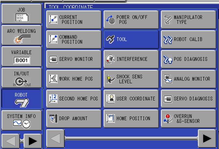
2.2. Select on which tool number you want to use. 64 tools are available when S2C431 =1
2.3. Select on “Utility” icon and select “Calibration” icon.
2.4. Next select which robot you want to perform TCP on.
2.5. Move the robot to a pointer as shown below and record this point as TC1. To record a point press MODIFY ENTER on the teach pendant.
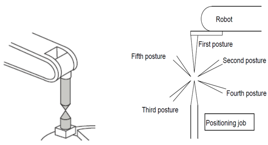
2.5.1 Record points TC2-TC5. I recommend teaching the next positions in quadrants, no more than 30 degrees tilt from the pointer. Ensure the robot posture sees a good amount of change in posture as this will increase the accuracy of the TCP. Doing this calibration in the robot work envelope will also assist in this.
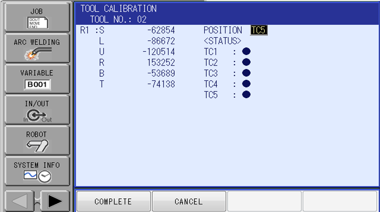
2.6. Once points TC1-TC5 have been recorded, select “Complete”.
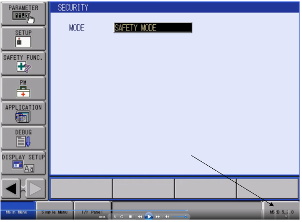
*Note. If the system has Functional Safety Unit (FSU), you will have to do a Functional Safety Reset in Maintenance mode. Boot into maintenance mode. Log into Safety mode. Password all 5555555555’s. Select on “FILE” icon then “Initialize” icon. Then select on “Functional Safety Flash Reset”.
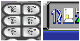
2.7. Using the roll about keys and robot frame coordinate, make sure the robot maintains an acceptable position on its TCP and does not drift from its location. It does not hold a good TCP repeat these steps until you get an acceptable TCP calibration. This will be crucial for setting up the camera calibration accurately.
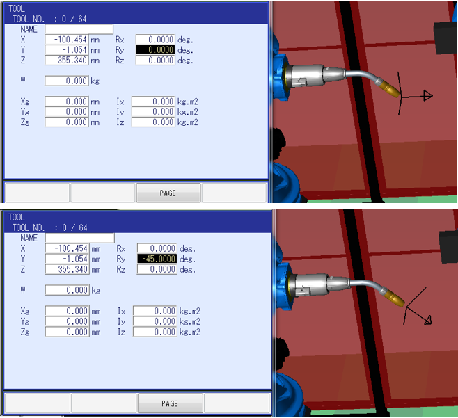
2.8. Next enter the correct values into RX, RY and RZ to change the Tool’s angle of orientation in relation to the operation of jogging in
that tool frame. See example below. +Z in tool frame should move down in relation to the angle of the tool.
2.9. Using the Weight, Gravity, Position Measurement auto calibration function
*Note this does not calculate Moment of Inertia.
This built-in feature on the controller is not 100% accurate and it is recommended that if the values are known for the tool, they should be entered in manually.
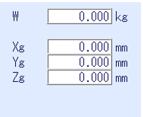
When performing this auto calibration, it populates 2 things:
- Weight of the tool.
- Center of gravity/mass.
Both measurements control and adjusts ACCEL and DECCEL parameters for the robot and effects cycle time and robot speed drastically. It is very important to have good numbers, otherwise damage to robot can and will occur. Leaving these numbers set to a 0 will give you a worse cycle time due to default parameter settings from Yaskawa defaulting to the maximum setting.
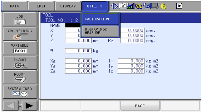
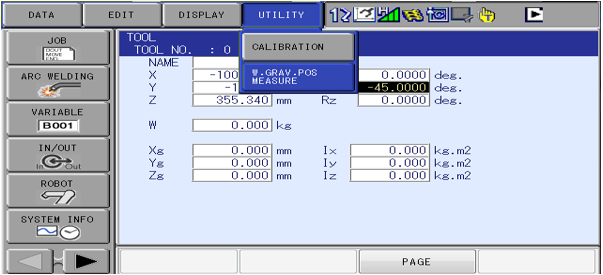
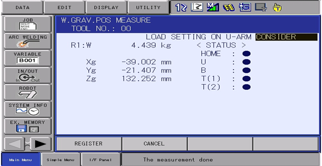
2.10. Select “Utility” and then “W.GRAV.POS.MEASURE in the tool file”.
2.11. Once in this screen, change from “NOT CONSIDER” to “CONSIDER”.
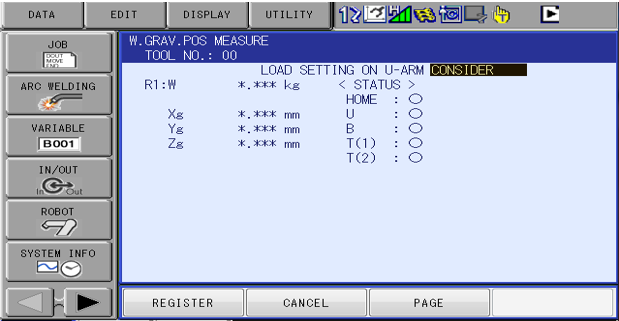
2.12. Press and hold fwd. on the teach pendant until all 5 bullets are blue. Robot will perform a routine and will stop moving when it is done. Select “REGISTER” when done.
Section 3: Creating a User Frame for Conveyor.
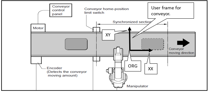
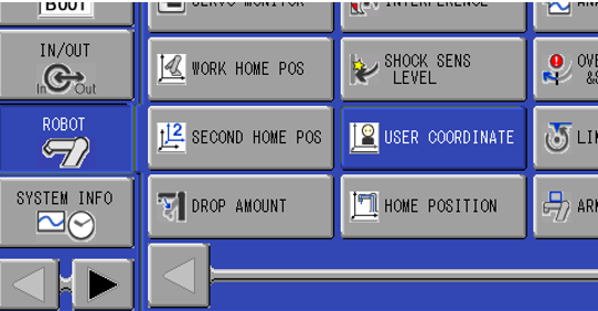
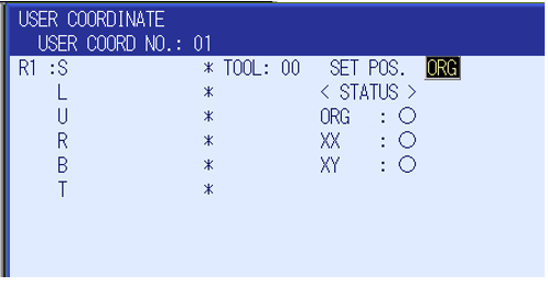
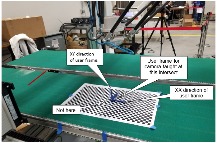
3.1. Select on “Robot” icon then select on “User Coordinate” icon. Next select which User Frame you want to use. This user frames XX vector defines the direction of travel for the conveyor.
3.2. Create a User frame to the conveyor as shown in picture. Using the edge of the conveyor to dictate XX will give you better data. If
the conveyor is not orthogonal to the robot, make the XX longer to give a better result.
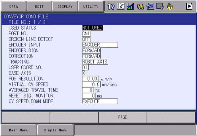
3.3. Assign the User Frame that was created in the Conveyor Condition File. This is located under “ROBOT” icon then select on “Conveyor Condition File”.
Section 4: Conveyor Menus and Conveyor Limit Switch
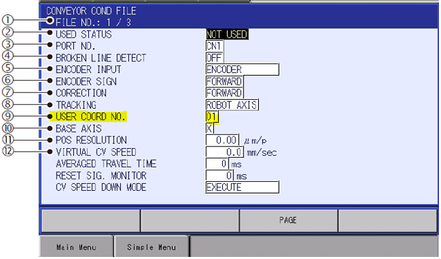
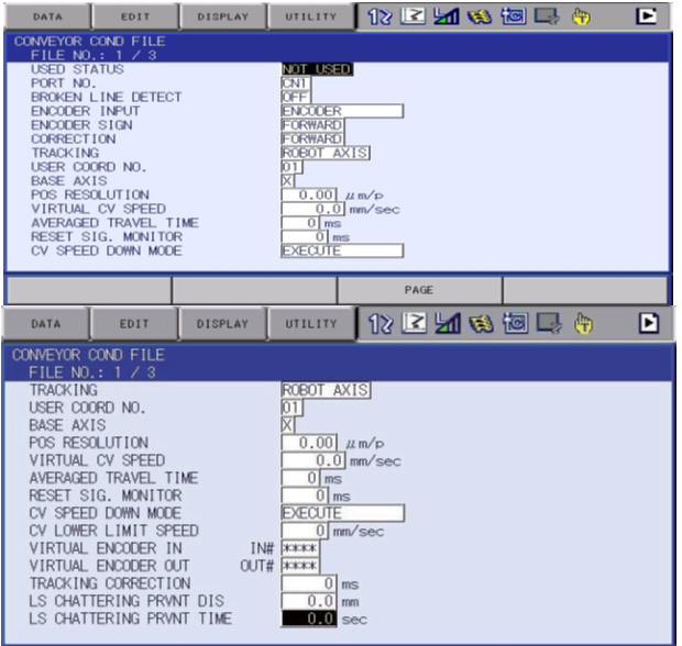
4.1. Conveyor condition file. For detailed information on individual settings please refer to the conveyor tracking manual. Configure the files per your application.
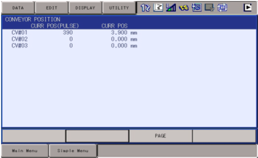
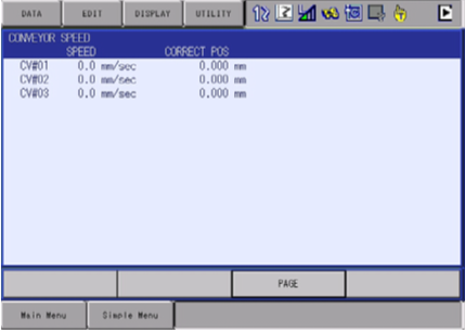
4.2. Conveyor Monitor Function There are three windows for conveyor monitoring as follows. Use the page key to navigate each window.
4.2.1. Conveyor position window. Monitor tracking in pulse and mm.
4.2.2. Conveyor speed window. Monitor tracking in mm/sec.
4.2.3. Conveyor tracking status window. Monitor that tracking has started
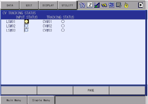
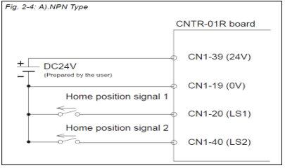
4.3. Verify tracking is working and displays in the condition position window when the sensor or device is triggered. If you are using an FS100 controller you must run a SYEND before it will see the Home LS triggered. Since the conveyor home-position input signals are used to reference the conveyor position, they should be in phase. It is recommended to connect this signal directly to the controller to eliminate dispersion caused by sequence scan time errors. Example below is for FS100 wiring.
Please reference the manual for your controller for wiring schematics of the limit switch (home position).
Section 5: Calculating position resolution
5.1 Since the controller automatically quadruples every encoder pulse count number. The conveyor positional resolution is set in in units of u. For example, setting the resolution 0.01 u/pulse bigger, will adjust the follow-up error of 0.01mm at the point that the conveyor moves for 10,000 pulses.

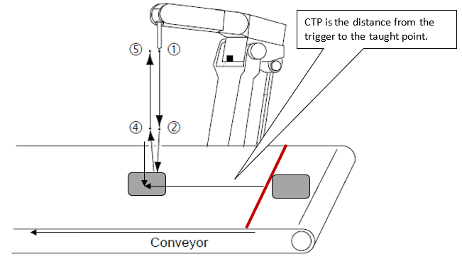
5.2 Referencing the drawing in picture above. Make sure the conveyor encoder is zeroed out. Next place the leading-edge part in front of the trigger. Place/move part until it trips the trigger. You should see the queuing instance populate in the CV tracking menu.
*If you have an FS100, you must execute a SYEND command before the LS trigger will be considered.
5.3 Jog the conveyor with the part on as far as you can, a minimum of 1 meter with a maximum of 21 meters. Measure the distance in mm from the trigger to the leading edge of part at new location. This will be your value for (L).
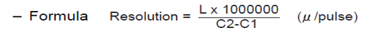
5.4 Formula for position resolution
Formula as follows. L x 1,000,000 divided by pulse counts of encoder.
*Note if the conveyor is not zeroed out before calculating the formula refer to the formula below.
* Enter the data into the column below in the conveyor condition file.
5.5 Verify and Adjusting Conveyor Positional Resolution. Create a job as shown below after conveyor resolution has been calculated and set in condition file. Please perform section 5.2 again. Next jog the conveyor with part to the location you want the part to be taught. This will be the move recorded in job example below on line 004 SYMOVL. The CTP tag value should match the distance traveled. This will be captured automatically when adding this move.
<Job Example>
0000 NOP
0001 MOVJ VJ=25.00
0002 MOVL V=300.0
0003 SYSTART CV#(1) ST=10.000
0004 SYMOVL V=200.0 CV#(1) CTP=100.000
0005 TIMER T=10.00
0006 SYMOVL V=200.0 CV#(1) CTP=100.000
0007 SYEND CV#(1)
0008 MOVJ VJ=25.00
0009 END
*Please refer to section 5.6 for conveyor instruction terminology before programming this job.
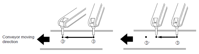
If the conveyor resolution is correct, the tool center point of manipulator synchronizes with the conveyor as shown below on the left. If it is not correct the robot may continually lead or lag and the distance will increase the farther the conveyor travels as shown in the right picture. If this happens recalculate pos res or manually update position resolution in small increments. Once you have verified tracking is good, move on to vision setup. Please note to take care while performing this calibration. This setting has a direct impact on accuracy of the application.
5.6 Brief overview of conveyor instruction terminology. Refer to the manual for examples with each instruction tag:
- SYSTART- This instructions indicates the start of a conveyor synchronized instruction.
- STP- Associated to the SYSTART tag is the distance from the trigger that the robot can start looking to begin tracking.
- OL- Associated to the SYSTART tag is a tolerance check for synchronized motion.
- SYEND- This instructions indicates the end of a conveyor synchronized instruction.
- SYMOV- These move instructions perform the actual conveyor synchronized motion.
- FPL- Associated to the SYMOV tag that is a feedback positioning level.
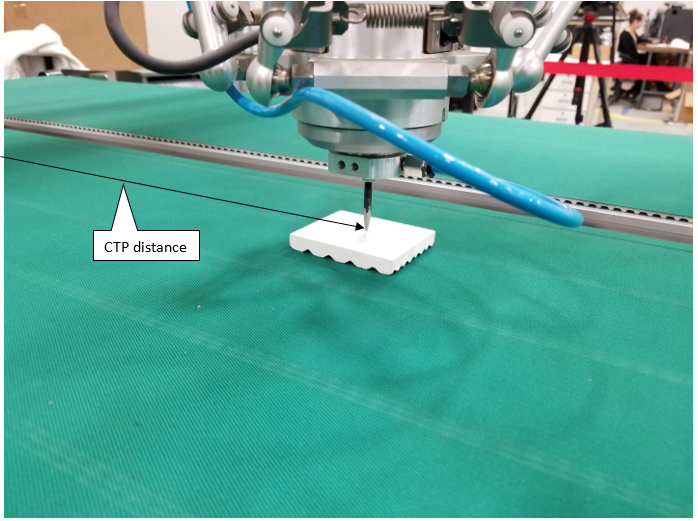
- CTP- Associated to the SYMOV tag, is the distance between the trigger and the point taught.
- CVQUE- Clears last instance of tracking.
- SYPICK/SYPLACE- These tag instructions are used for picking and placing motion with a single instruction.
Click on the attachment at the bottom of this article for an example of conveyor tracking only and high speed picking.
Section 6: Verify Proper MS2D Setup
6.1 Select [IN/OUT] from main screen and then select [Network Input]. Note. This signal is the MS2D heartbeat signal. It should alternate from 0-1 once per second. If it does not, verify that MotoPlus is set to run at startup and that the MS2D MotoPlus application is loaded properly from maintenance mode.
- For DX100 / FS100 display I/O point 25240
- For DX200 / YRC1000 display I/O point 27240
6.2 A value of 1 indicates the license file is loaded and verified. A ‘0’ indicates that the license is not valid. If a value of 0 is present, please contact your local Yaskawa representative.
- For DX100 / FS100 display the I/O point 25241
- For DX200 / YRC1000 display the I/O point 27241
Section 7: IP Address settings for Robot controller, Camera and PC
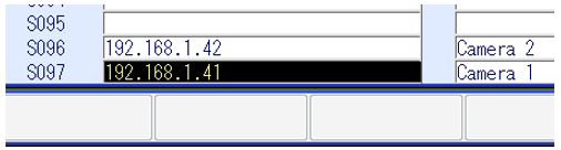
7.1 Enter the camera IP address into the following string variable content location[s]: (Variable/String). This can be found by selecting the Variable Icon/String on the Teach Pendant. Enter description in the name column. Example: Camera_1, Camera_2, etc.
FS100 DX200/YRC1000
- S97: Camera 1 0.0.41 192.168.1.41
- S96: Camera 2 0.0.42 192.168.1.42
- S95: Camera 3 0.0.43 192.168.1.43
- S94: Camera 4 0.0.44 192.168.1.44
- Power down the robot and all cameras.
- Power up the cameras first and let them completely boot
- Power up the robot control
- The sequence 7.2 – 7.4 should be done anytime a change is made to any I/P address, or file saved to the camera settings of the system.
*Changing the IP Address of the FS100 controller to an address outside the 10.0.0.x address range requires that the pendant address is also changed to stay within the subnet mask.
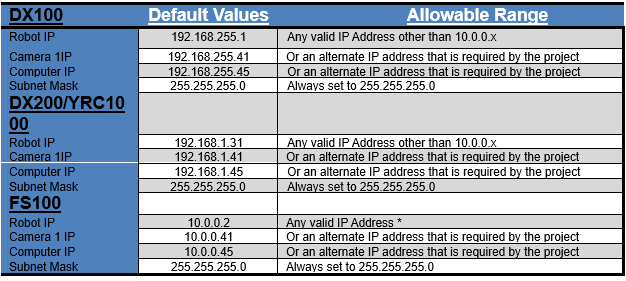
7.2 Default values for IP addresses as shipped from Yaskawa.
Section 8: Cognex Vision Setup
8.1. If required, install Cognex In-Sight Explorer software (Ver. 4.5.X or later) on the PC. Insight Explorer can be downloaded from http://www.cognex.com/Support/InSight/Software.aspx
8.2. Disable the Windows Firewall as it can interfere with Camera and Robot communications.
8.3. If the laptop IP Address is already set correctly, skip to step 4.8
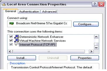
8.4. In Network Connections on the PC, right-click the desired connection (typically “Local Area Connection”) and select “Properties”
8.5. From the “General” tab, highlight “Internet Protocol (TCP/IP)” from the “This connection uses the following items:” list and click on the “Properties” button
The actual IP Address will be dependent on the addresses used for the robot and camera.
8.6. From the “General” tab, select the “Use the following IP address” radio button and complete the settings
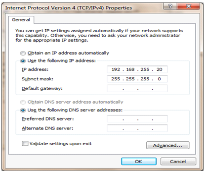
8.7. Click ‘OK’ to close the “Internet Protocol (TCP/IP) Properties” window
8.8. Click ‘OK’ to close the “Local Area Connection Properties” window
8.9. Start the In-Sight Explorer program on the PC and Select ‘Get Connected’ from the Application Steps menu on the left.
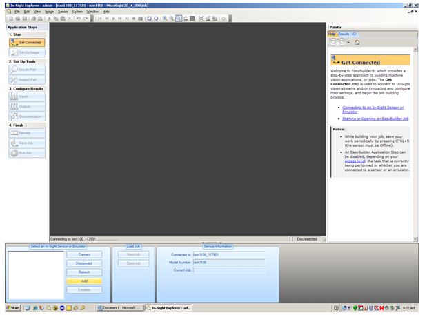
-- Note: If a new camera is being used, In-Sight will not recognize it. The screen will continue to say, “scanning network”
-- Under system menu select “Add Sensor/ Device to Network”
-- Dialog boxes may pop up stating” The emulator was not started because no In-Sight devices were detected on the network…” and “No devices were found to add to your network” Click “OK” on these.
Select the ‘Add’ button from the menu in the lower left.
8.10. Select the camera from the list, and then complete the settings.
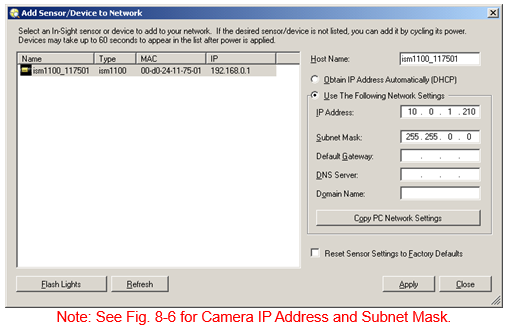
8.11. Change “Host Name” to “Camera 1” thru 4 depending on number of cameras used.
8.12. Click ‘Apply’
8.13. A message box appears stating “This will change the network settings of the device. Any existing communications with the device will be broken. Are you sure you want to continue?”, click ‘OK’
8.14. A message box appears stating “Network settings changed successfully.”, click ‘OK’
8.15. Click ‘Close’
8.16. Select the camera in the lower left window and click ‘Connect’
8.17. Make sure the camera is ‘Offline’
8.18. Click the menu item ‘System’ -> ‘Update Firmware’ and note the firmware version of the camera
8.19. If the camera firmware version is lower than 4.05, you will need to upgrade the camera firmware. If not, skip to 8.33. Do not upgrade the camera firmware higher than the 5.7.3
8.20. If the camera firmware version is higher than 5.7.3, you will need to downgrade the camera. If not, skip to 8.33. Do not downgrade the camera firmware lower than 4.10.3 (Using Insight Explorer version 5.3.0).
8.21. If you changed the camera firmware, close and restart Insight Explorer to re-connect to the camera from the lower left window and verify in “offline” mode.
8.22. Highlight the camera in the “In-Sight Network” window
8.23. Select “View” ->” In-Sight Files” from the menu if not already visible on screen.
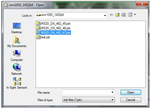
8.24. Select [File] [Open Job…]. Load the latest camera template job ‘MS2D_XX_XXX.job’
If camera was integrated by Motoman, then there will be template jobs already. If not
drag and drop your template job into menu. The MS2D template must be used to start a camera job for the MS2D application to communicate correctly.
Section 9: Setup and calibration
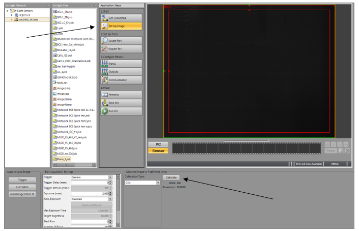
9.1 Under the “Application steps” in middle of the screen select on “Setup Image”
9.2 Select on “Calibrate” with calibrate type set to grid.
9.3 The screenshot below will pop up. *Note. These settings below will be dependent on your application. This is what was used for our setup and testing.
9.4 Once you have determined the parameters below needed for your application select on “print grid”
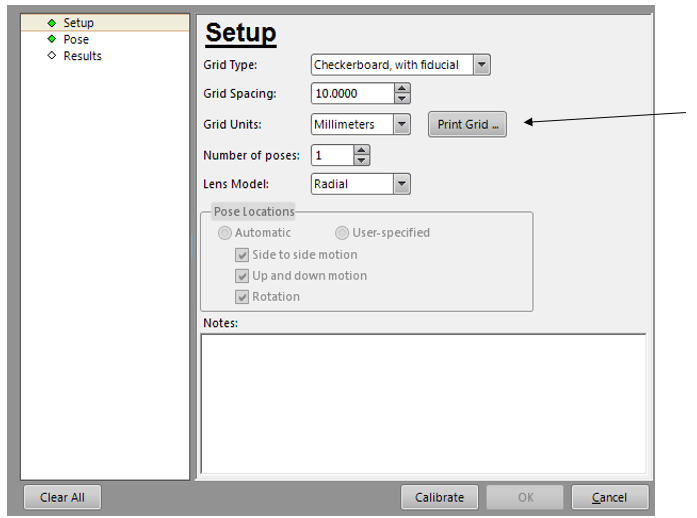
*Note. Verify after printing the grid that the squares represent the correct amount selected. Example would be that the grid spacing above is 10mm. Verify that the squares printed are 10mm.
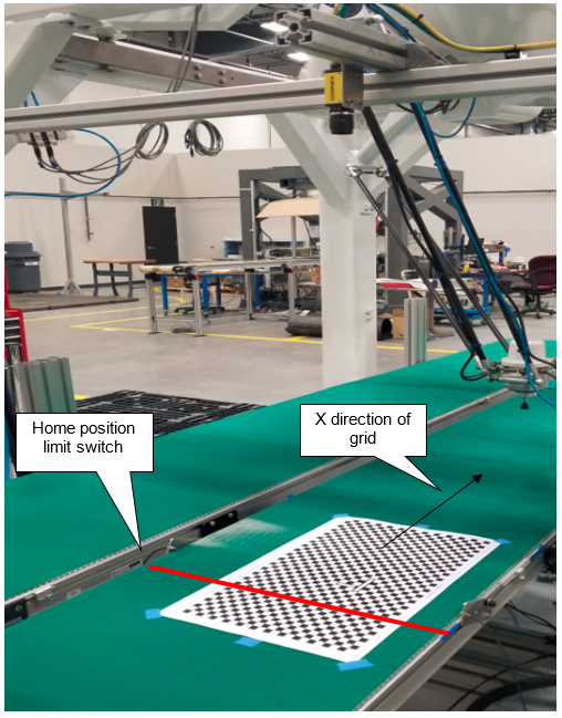
9.5 Place the grid on Conveyor with the X direction going with the length of the Conveyor. Taping it down is recommended to help keep the grid in place.
9.6 Click on “pose” and click on “trigger”. This will take a picture of the grid. Square the grid up in relation to the camera view while using the trigger to update orientation.
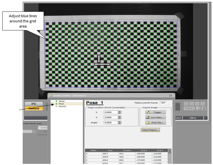
9.7 Once the calibration grid is squared select on “adjust region” and adjust the blue lines as shown below. Hit “Enter” on the Keypad to capture settings.
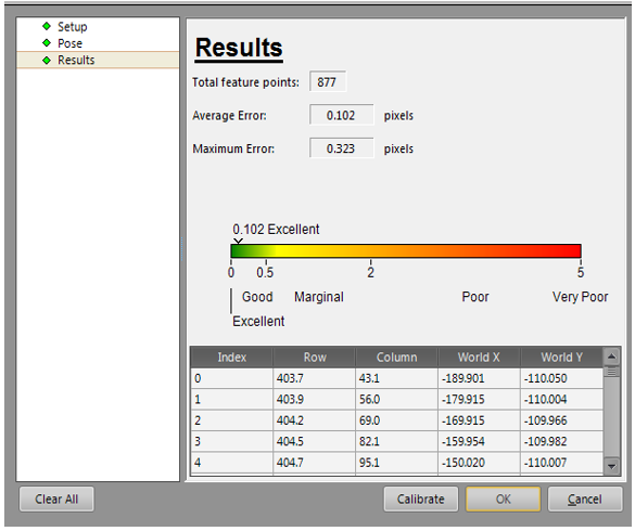
9.8 Click on “calibrate” then click on “ok”. As shown below you can see the calibration results.
9.9 In the top left corner select on “File” then “Save job
Section 10: Creating a Userframe with the robot to grid for camera.
10.1 After calibrating the grid with the robot, trigger the home limit switch so the que reads 0.
10.2 Move conveyor down with grid still taped to original location to where the grid is in robot work space while monitoring the conveyor’s traveled distance. It is recommended the entire grid be in the robot’s working envelope. Write down the distance the conveyor traveled in mm. This is your CTP data that will get assigned to your SYMOVL tags.
10.3 Teach a new user frame in the intersect of the fiducial intersect.
10.4 Next we will create a job that will reference the user frame we taught in section10.3. There are two ways that you can teach this job. If you use example (b) please peform example (b) below and move on to section 11. If you use example (a) please perform example (a) and follow steps 10.5 and 10.6.
a. Create a relative job. This will be called based on the user frame that was taught in section 10.3. Example: In your master job, Call job (Pick) UF#1. In the pick job all motion is stored in X,Y,Z format and the SYMOVL is updated from the camera with the “inspect” and “adjust” macros as shown in the attached MotoSight 2D video.
b. Create a job standard pulse job called “Pick”. Once inside the job press on the “inform key” then select on “motion” next select on “SYMOVL P001 CTPXXX.XXX. The camera will update assigned P001 variable with X,Y values. However, you will need to manually plug in the CTP data in the tag that was recorded in section 10.2.
10.5 Place the edge of the part in front of the home limit position switch.
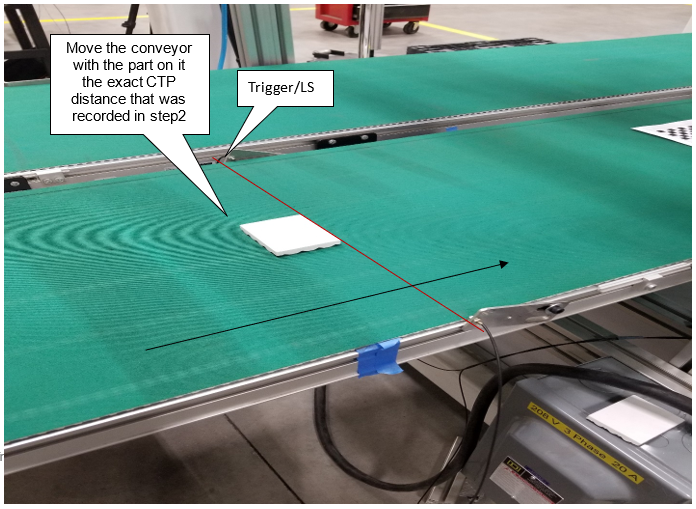
10.6 Manually move the conveyor the distance of the CTP data recorded in step 10.2.
In the relative job created called “PICK” create a point using a “SYMOVL V=200.0 CV# (1) CTP=XXX.XXX” with the part taught at the pick location you are trying to achieve. The CTP data tag will populate with the distance from the trigger to the TCP location of the robot as shown in the picture below.
10.7 EXAMPLE JOB?????
Section 11: Setting up the Motosight 2D app on controller
11.1 Click on the MS2D app in the bottom right corner
11.2 If dialog box appears asking for IP address for camera, enter the IP address of the camera. If dialog box appears with “can’t connect w/ 10.0.0.2” follow steps 11.3-11.8. If app launches with no problem jump to step 11.9.
11.3 Check Network Input for valid MotoPlus license and heartbeat bit.
- YRC1000, DX200: 27241 à 1; and 27240 à toggling between 0 and 1
- DX100, FS100: 25241 à 1; and 25240 à toggling between 0 and 1
11.4 Check S97, S96, S95, S94 for correct IP address for camera#1, camera#2, camera#3, and camera#4
- After setting string variable you must cycle the controller power.
11.5 Ping camera IP and robot IP from your laptop.
11.6 Confirm MS2D camera template job is loaded on camera.
11.7 Confirm controller IP is correct on camera template job
- Communication à TCP/IP
11.8 Open command prompt (CMD) on your laptop and type:
- telnet xxx.xxx.xxx.xxx (where x’s represent your camera IP address)
- user: admin
- password: <null>
- gi <ENTER>
- camera should respond with software version and parameters
- If no connection, see camera network tab: TELNET port = 23; Ethernet/IP selected
- If connection OK, power OFF robot and camera. Power camera ON and let camera reboot fully (may take a couple of minutes); then turn robot back ON.
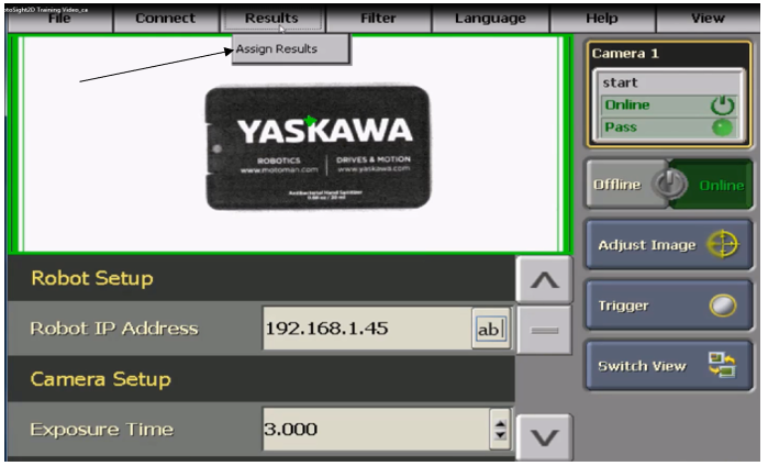
11.9 Once the app is open. Select on “results” then “assign results”
11.10 Next select the tool pattern that was created in Cognex and assign the variables according to your application needs.
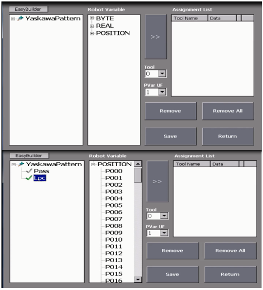
11.11 After assigning the correct variables that you are using, select the correct “tool” and “PVar UF”. Then click on “Save”
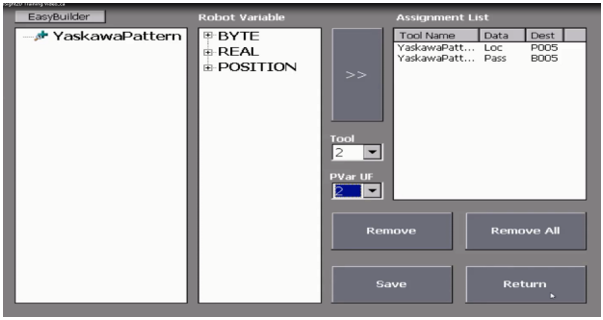
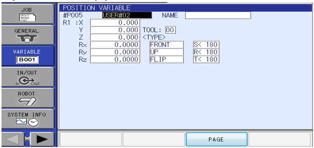
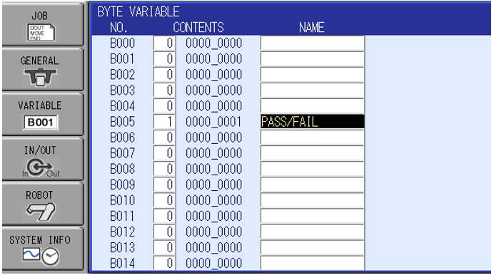
11.12 When the camera triggers you should see data populate into the Pvar that was selected with the correct user frame associated.
Comments
0 comments
Please sign in to leave a comment.