Introduction
Our controllers have a background process which runs continuously to manage input and output signals. That process is referred to as “Concurrent I/O” (CIO). The CIO process starts when the controller is powered up and runs constantly, in parallel with any INFORM jobs that may have started.
This document will provide an overview of function and use of Concurrent I/O This is a basic introduction to what can be a complex topic. For detailed instruction on modifying the CIO Ladder, review the Concurrent I/O manual for your controller (links below), and check out our offerings from the Yaskawa Training Academy. The Concurrent I/O Manual for your controller is also mandatory reading for those who will be making modifications.
The Basics
The CIO Process works like a PLC for the robot. Input signals are monitored, and output signals are raised based on logic Yaskawa or you have specified. Like with PLC’s, there is a ladder and ladder logic that are used to define what the CIO Process will do.
System and User Ladders
Our ladder is divided in to two parts:
- A System ladder to define how the controller will process signals to implement the normal operation of the robot and
- A User ladder that is used to define how signals will be processed to meet the needs of a specific user application.
Anyone can view the System ladder to understand basic controller functions, but it can only be modified by Yaskawa-authorized personnel. The User ladder can be modified by anyone with Management Mode or Safety Mode security permissions.
Note: Yaskawa Motoman creates different ladder programs to support different applications (like welding or handling). Two robots of the same model may have different features included, which may also result in different ladders. Do not attempt to copy a complete ladder between two systems. It is likely you will cause problems by implementing a ladder that does not match the target system. It is better to review and test changes on one system and then replicate only those changes as needed on other systems.
Classification of I/O Signals
There is a Concurrent I/O manual for each of our controllers (see links below) that explain what signals area available to use and their purposes.
|
Controller |
Manual Name / Link |
|
YRC1000 |
|
|
YRC1000micro |
|
|
DX200 |
|
|
DX100 |
|
|
NX100 |
|
|
FS100 |
Of particular importance, in each manual is a section titled, “Classification of I/O Signals”. This provides the numbering system we use to organize the thousands of signals available. An excerpt, showing some commonly used signals for the YRC1000 controller is shown below.
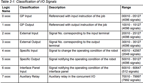
Tip: remember “odd man out” to differentiate between input and output signal addresses. Output addresses always start with an odd number.
CIO Ladder Editing and Update
There are multiple ways to view and update the CIO Ladder. There are “Ladder Program” and (optional) “Ladder Editor” functions available from the teach pendant. (Find those under the IN/OUT menu on the pendant.) See the Concurrent I/O manual for your controller (links above) for more detail. Page 336 of the YRC1000 manual is an example of where to find this information.
You can also download the ladder as a text file and view or change it on a PC. The CIO Ladder is stored in a file named CIOPRG.LST. It can be saved from the pendant by selecting EX.MEMORY, SAVE, I/O DATA, C.IO PGM. This creates a file named CIOPRG.LST on the USB Memory stick.
The syntax used in the CIOPRG.LST file is cryptic. It is explained in your Concurrent I/O manual. The easier way to get started is to use one of our Ladder Editor options. We also sell a Ladder Editor program for Windows PC’s. This Windows program presents a graphical view of the ladder and can be used to edit the CIOPRG.LST file, check syntax, search for signals, etc. Contact your sales representative for pricing and details.
Common Problems and Solutions
Loading an invalid ladder file into a running controller would cause serious problems. Basic functions could stop working and safety signals may be processed incorrectly. Consequently, there are safeguards to prevent people from accessing critical rungs or loading an invalid file. As modifications are made online, they are held in memory until they can be compiled (reason checked) before running. An improperly constructed CIOPRG.LST file will not load on to the controller. This is another reason to use one of our Ladder editing solutions rather than try to update the text file manually. Other common problems:
Problem: Unable to make any changes to the CIO Ladder.
Solution
| Check to make sure you are editing the USER section of the ladder. The System ladder can only be modified by authorized Yaskawa personnel. Any changes you need, must be done in the USER ladder. To the right are screen shots of editing sessions with the Ladder Program, Ladder Editor and the CIOPRG.LST file that indicate which section of the ladder is being edited. | 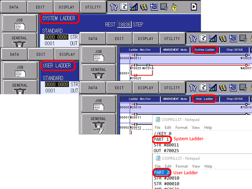 |
Problem: “Attempting to End Multiple Rungs with the Same Output Relay.” Cannot find where that Output Relay is Used
An output relay may only be used as an output once, in the entire ladder (both System and User portions.) You will receive an error message if you attempt to use the same output on more than one rung. However, after receiving the error message you are unable to find a rung where that output is in use.
Solution
There are two possible conditions that can cause this. The Output Relay may already be in use in the System Ladder. Search the System ladder to see if this is true. You will need to understand what signals are triggering that output and design rungs in the User ladder to use those same input signals.
Secondly, the output signal you are trying to use may already be in use as part of a Block Move (BMOV) or Group Move (GSTR/GOUT) command. These commands operate on one or more bytes at a time. The bit(s) you may be trying to map may already be part of one or more bytes being controller by a BMOV or GOUT command. Most commonly, the issue is BMOV, described below.
|
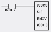
For example, the command: |
This is just like having individual rungs to move each bit. |
|
|
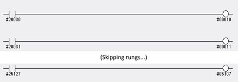
STR #70017 BMOV 20030, 510, 00010
Will move 510 bytes of data starting at address 20030 to the address 00010 when #70017 (controller power) is on. (This is how External Inputs are mapped to General Purpose Inputs.)
|
STR #70017 AND #20030 OUT #00010 STR #70017 AND #20031 OUT #00011 ========= STR #70017 AND #25127 OUT #00517 |
Viewing the same BMOV in the Ladder Editor:
|
The graphical ladder view of the above BMOV looks like this:
|
Which has the same effect as 4,080 (510*8) individual rungs.
|
Solution
If you want control of one or more bytes within the above BMOV, you will need to change the ladder so that your bytes are not within the range of the BMOV. This involves breaking the BMOV in to two pieces and inserting your change in the middle. For example, suppose you wanted to use some of those External Input addresses (2xxxx) for some other purpose. Maybe they are going to be mapped to Specific Input addresses (4xxxx) to control the robot. Let us take 4 bytes right out of the range of that BMOV – say, 20100, 20110, 20120 and 20130. We will need to change the ladder to have a BMOV for 20030 through 20090 and then 20100 to 25120. The rungs would look like this:
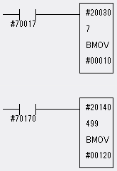
How did I come up with the addresses and number of bytes?
We start at #20030 and can move 7 bytes before we hit the 20100 address that is to be broken out. (20030 + 70 = 20100). Remember, the last digit of the address represents BITS in the byte.
Skip 4 bytes (20100, 20110, 20120 and 20130) and we know our next BMOV starts at 20140.
Recall, the total number of bytes covered in the original BMOV was 510. We have already accounted for 7 + 4 = 11. Therefore, the next BMOV must handle
510 – 11 = 499 bytes.
The destination address for our last BMOV is calculated similarly. We started at 00010 and used 7 bytes (00010 to 00070). We skipped 4 bytes (00080 – 00110). So, now we pick up at 00120.
(In the example above , auxiliary address #70017 is used. This coil is used to signify “Controller Power is On”, so it will always be true. Technically, it can be omitted but was included to align with the original ladder commands found in a “production” ladder.)
Comments
1 comment
Diagram shows "registers", but they're not mentioned again. What are they?
Please sign in to leave a comment.