Introduction
This document will help walk through the process of enabling, setting up and calibrating your system for coordinated motion. This will cover the steps needed to complete this in MotoSim, as well as a real controller. There is slight variation of the steps needed between the two.
Setup
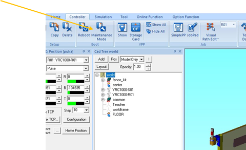
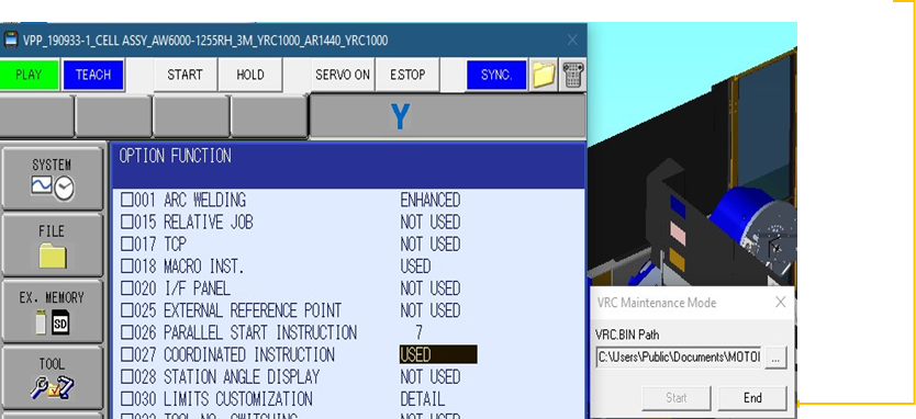
| 1. MotoSim - Boot Controller into maintenance mode. |
|
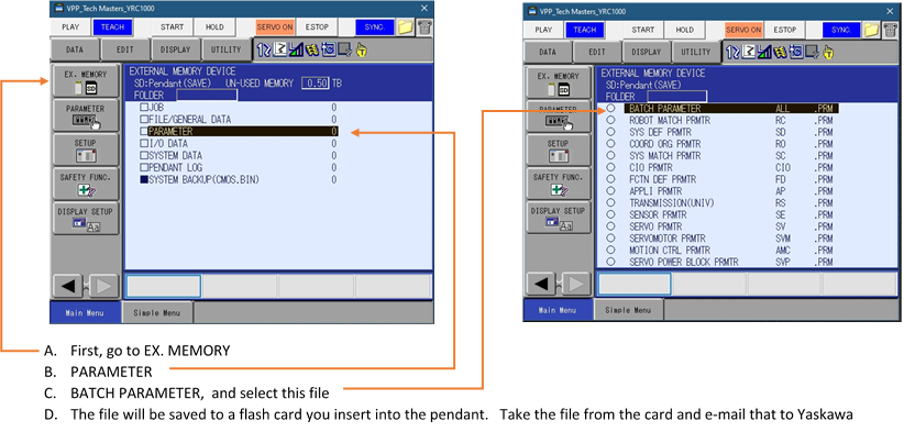
2. Real Controller - The parameter file will have to be updated to turn on coordinated motion. You will have to contact Yaskawa and send the file in to have that feature added. You will need to obtain a onetime password from Yaskawa in order to load the updated parameter file.
If you are on a real controller, then you can skip to page 7. Starting on STEP 7
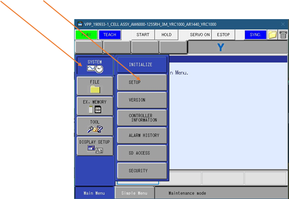
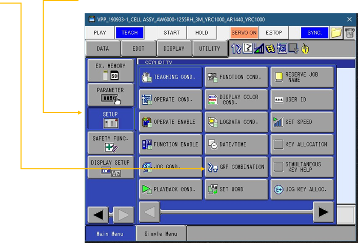
3. Click on SYSTEM and then SETUP
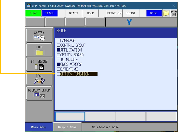
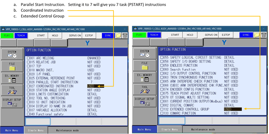
4. Under setup, you will click on OPTION FUNCTION
5. Under option function, there are a few items you will want to enable when setting up a system with a positioner - like an Arc World.
6. After all options you need are turned on, re-boot controller to normal power up by clicking END on small window behind pendant screen.
7. Once you are powered back up in normal mode, go to SETUP.
8. GRP (Group) Combination
9. In GRP Combination, setup the groups needed to work together.
a. R1+S2 or R1+S3 for standard groups
b. S1+S2+S3 for extended control group (Used to sweep positioner) 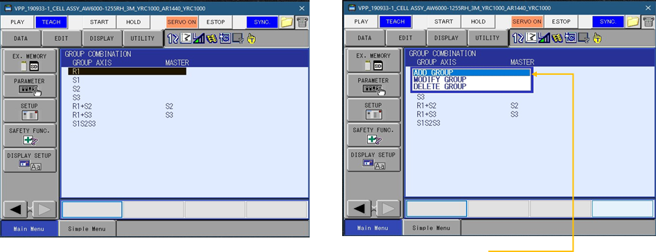
c. Create any group you need by selecting on any that is already created and then click on ADD GROUP.
10. Click on ADD GROUP, it will show 4 lines for Group combination set. Here, it is set up has R1+S2 (Side A), with S2 as master.
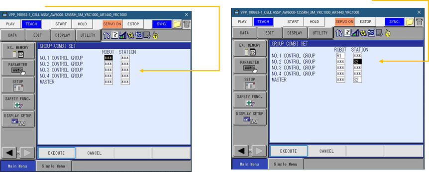
11. When the group combo is setup as R1+S2:S2 or R1+S3:S3, the station is master. This is used for coordinated motion.
12. With extended control group turned on, you can create a S1S2S3 setup. Used to sweep positioner and maintain S2 & S3 in the flat position to clear floor. There is no MASTER when setting up this group.
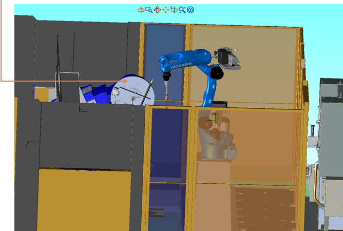
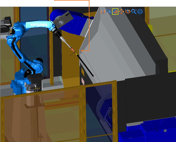
13. After you have your groups setup, calibrate the robot with the positioner. In the case of a Ferris wheel style of positioner, you will have 2 sides to calibrate: station A (S2) & station B (S3). You will not calibrate to S1 (Main sweep). If you have something on the positioner that can be used as a pointer to calibrate, that will work great. If it is not on or close to the center line, then it will be more accurate. If you are too close to the centerline, then you can get an error, “Defective Taught Point”. If your tooling or parts do not have anything to use as a pointer, then make one to use as the picture shows below.
14. Once you have something to calibrate to, go to ROBOT, then click on ROBOT CALIB.
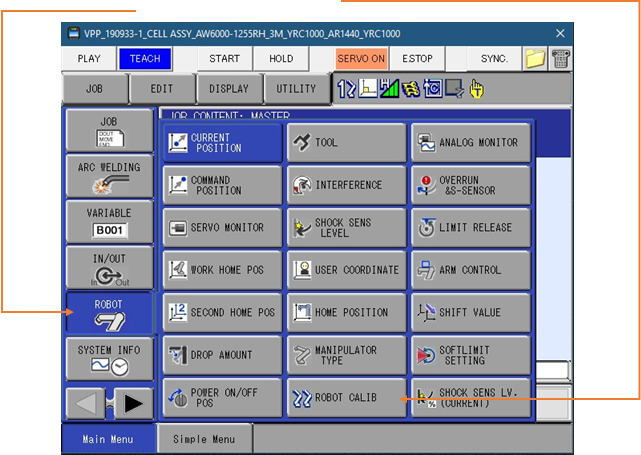
15. This will open the robot calibration screen. Then choose what group to calibrate the robot to.
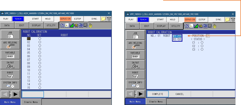
A. Each station will have to be rotated to the robot side for calibration. So, you can calibrate R1+S2(Side A) or R1+S3(Side B).
16. When you choose a robot + grp combo, it will show the following positions to be taught. C1, C2 & C3.
A. Calibration should always be done with the pointer or pick location to be closer to the robot at start for C1.
B. Jog the robot to that point and start with a tool posture you are pretty sure you can maintain throughout the rotation moving positive (Top of fixture, forward).
C. There, C1 will be taught. Then jog station about 20 degrees and move robot to that point with cartesian move only. Do not change tool angle. That will be C2. Make sure to change menu to C2, prior to modifying that point.
D. Rotate station another 20 degrees or so, and jog robot to that point. Make sure you are on C3, and then hit modify, enter. Once all 3 points have been taught, hit COMPLETE at bottom of screen. You will pick the C# here. Hit MODIFY here, then ENTER.
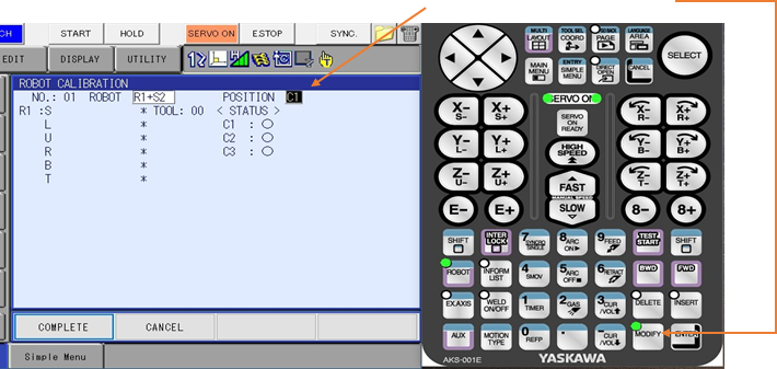
17. Here is an example of a starting point of the stations which will be C1.
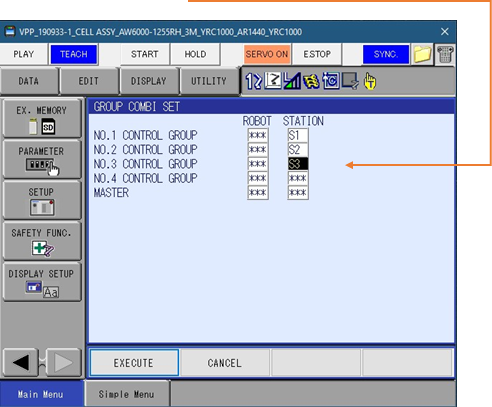
18. When teaching a job that will sweep the positioner, the group set will be S1S2S3 as shown. It will have all 3 stations on the program line.
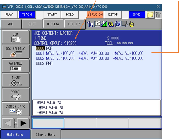
19. When teaching a job using coordinated motion, the robot and station will show being programmed on the same instruction line. In the header you will see R1+S3:S3 (in this case), where S3 is master. If you need to jog the robot along with the positioner and maintain tool angle set where it currently is, then hit the 7 key. This is also to turn on SINGLE/SYNCRO. When it is enabled, a double robot icon at the top of the pendant will be displayed.
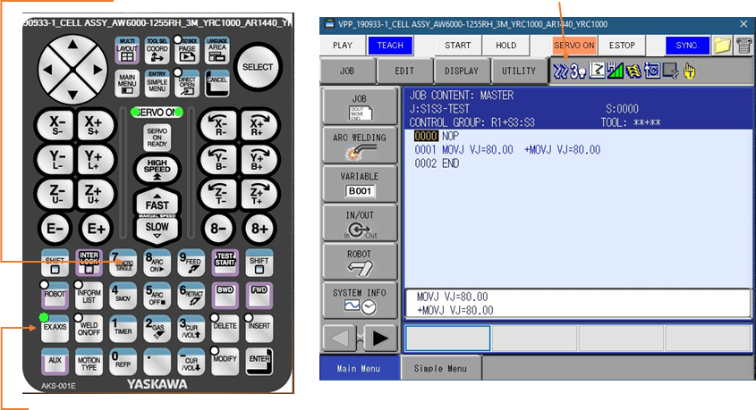
This will only work if you have the external axis active.
20. Here is an example of move types with a station tied to the robot. On line 1, the station and robot move together, but in a simultaneous motion.
On line 2, the robot and station are coordinated throughout the path. There is only SMOVL, SMOVC and SMOVL. Not SMOVJ.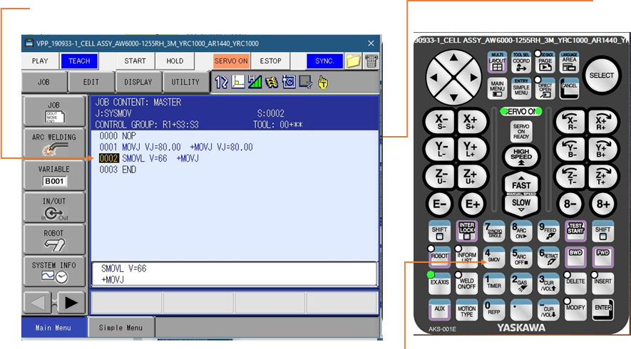
In order to change motion type, click on the 4 key, or SMOV key. This will toggle from MOVL to SMOVL (for example) Pressing the MOTION TYPE key will toggle though linear, circular and spline, plus joint (when not in synchronous moves).
Comments
0 comments
Please sign in to leave a comment.