Calibration
For coordinated motion between a robot and a station axis, positioning calibration must be performed. This calibration will define the positional relationship between the two devices.
Tool calibration
Prior to any calibration, accurate tool data (TCP) must be obtained. The UTILITY menu provides an automatic method to calculate only the X, Y, and Z dimensions of the tool data from 5 TC reference positions taught with a variety of orientations.
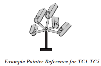
This resulting calibration data represents the offsets, in millimeters, from the flange of the T-axis to the desired tool control point on the end-of-arm tooling.
To calibrate the X, Y, and Z elements of the TCP data, perform the following:
1. Choose a fixed point in the robot cell.
2. In TEACH mode from MAIN MENU, choose ROBOT.
3. Choose TOOL.
4. Choose UTILITY in the Menu Area.
5. Choose CALIBRATION.
NOTE: To clear the set bullets, choose DATA in the Menu Area and choose CLEAR DATA. Choose [YES] on the “Clear data?” screen.
6. Enable Servo Power and choose any COORD except TOOL to jog the desired TCP to the fixed point, then press MODIFY and ENTER. The first point, POSITION TC1, is now accepted and the bullet is set (●).
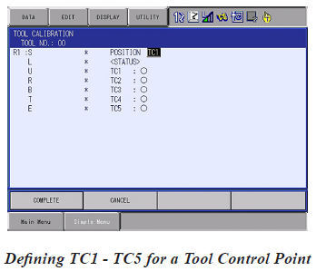
7. Press SELECT. Cursor to the next identifier POSITION TC2; press SELECT.
8. Repeat Steps 7 and 8 until TC1 through TC5 have position data set. Obtain as much variation as possible in orientation between the five TC points.
NOTE: To view the position where a TC point was set, use the FWD key to move to the desired TC point. When the highlighted TC number stops flashing, the robot is at that TC point set location.
9. After all five TC points have been entered choose COMPLETE.
Upon completion, the new data for the XYZ dimensions of the tool is displayed.
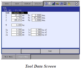
10. Manually enter any required Rx, Ry, or Rz data in degrees.
Group Combination
Prior to calibrating the robot and the station, the combination must be established. This is done in the Management Security level.
To check and establish Group Combinations, perform the following:
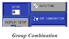
1. Choose SET UP, choose Group Combination.
2. Verify existing combinations.
NOTE: In a default system, only the single groups are identified, with no combined groups. If combined groups have been added, they will be indicated using a “+” character.
3. Press SELECT to access the drop down ADD/MODIFY/DELETE.
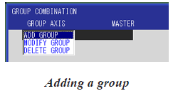
4. After selecting ADD GROUP, cursor on No. 1 Control Group and press SELECT.
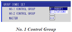
5. Choose the robot R1-R8.
6. For No.2 Control Group, to calibrate multiple robots, choose a second robot.
or
Choose STATION and select the desired Station.
NOTE: For coordinated motion and calibration purposes, a Master device must be selected.
7. Choose the Master device.
8. Choose EXECUTE.
When multiple combinations are desired, repeat the above until all desired groups are identified.
Single Motor Station calibration
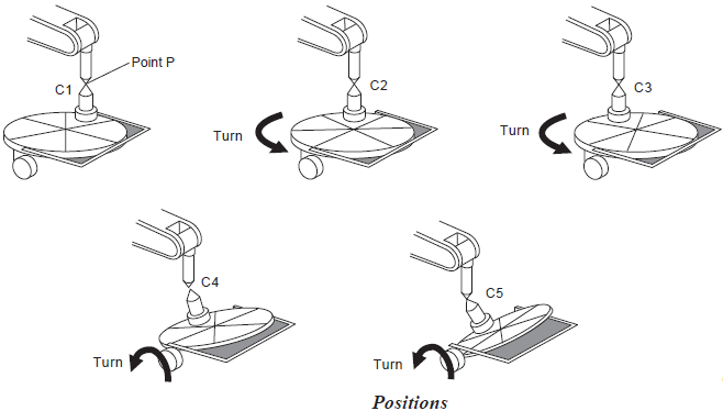
Calibration of a single motor station to the robot requires the teaching of three points. These align the TCP of the robot with a arbitrary point on the station in three different rotational positions.
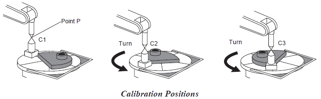
At these points, the robot should have the L axis approximately vertical and the U axis approximately horizontal. Calibration with either axis at near the axis limits will not allow accurate calibration. The tool posture should remain the same during the programming of C1-C3. Sequencing of the positions as close to those indicated will result in the best calibration.
To calibrate a single motor positioner, perform the following:
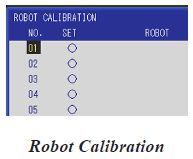
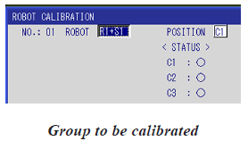
1. Choose ROBOT, choose Robot Calib.
2. After verifying that the equipment is not yet calibrated, cursor to the first open calibration element and press SELECT.
3. In the calibration screen, set the desired robot and station.
4. Choose the calibration point (C1-C3).
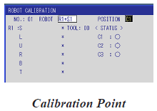
5. Jog the robot to the desired position, press MODIFY and ENTER.
6. Change the calibration point, jog the robot, MODIFY and ENTER.
7. With C1-C3 programmed, choose EXECUTE.
Comments
0 comments
Please sign in to leave a comment.