Scope and Purpose
This article the procedure for the setup of the MS2D option with a mobile camera.
Software Requirements
- Software version: Any current MS2D application
- Ladded modification - No
Installation Procedure
- Start off with a properly taught TCP with a pointer affixed to the tooling. Please use the 5-point calibration method and test for a proper roll about. This needs to be as good as possible, this will be used to teach user frames and accurate tool data is required for proper results.
- Prepare the area for calibration. You will need a part or a test part to teach the camera to, a calibration grid from the Cognex Insight Explorer, any lens and lighting that will be used.
- First connect to the camera, you can this with your laptop and Cognex Insight Explorer. Once connected put the camera offline and load the appropriate MS2D template job. The correct template can be found using the spreadsheet included with the system, it is based off camera firmware version. If you have MS2D 5.4.2 or above use one of the templates with 1 at the end.
- Move the robot so that you can see the feature you wish to teach to with the camera. You will then need to adjust the focus, aperture, and lighting to get a clear picture. This will be the work distance you wish to do your inspections at. Save this position in a job or position variable, this will be your temporary inspection position.
- With the pointer tool chosen as your active tool, teach a user frame on the face of the part you were looking at with the camera. This is a “dummy user frame.”
- Forward to your saved temporary inspection position. You will need to create a camera TCP for the camera on the mobile inspection position. Please choose an empty file for this, or clear one out. Select this empty tool as your active tool and save it as a position variable relative to the “dummy frame” that you created in the last section. Note the number in the Z element.
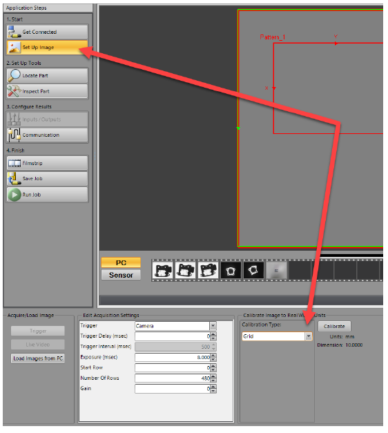
This will be the distance from the flange of the robot to the ORG of the frame. We will use this distance to calibrate the camera. - Go back into Insight Explorer. Under the Application Steps select SET UP IMAGE. Select GRID as the calibration type and click on Calibrate.
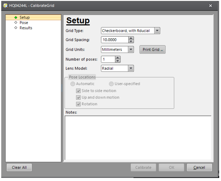
- Next will be the popup where we setup the calibration grid we need to print. You will want a Checkerboard with fiducial, and you’ll need to select your grid spacing. Grid spacing should be chosen based on your FOV and current application, and camera resolution. Each square should be at least 15 pixels wide for the camera. Once setup you will need to print this. When printing the goal is to fill the FOV, this will assist the calibration and the filters such as Transform.
- Print the grid. Please measure the grids and ensure the squares are the size you have requested. You will want to mount this grid to an area the robot can move to in the work area. Ensure all the lighting and lens for the camera are set.
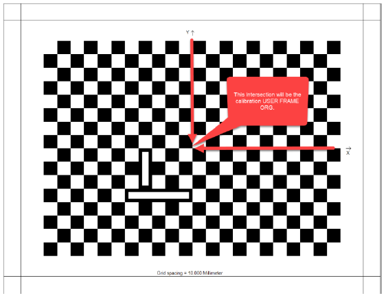
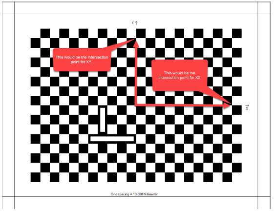
- With the pointer TCP set as your active tool you will need to teach a user frame on the grid. This will then be the Calibration Frame and the data from the camera will be returned to the robot relative to this frame. It is important that it is taught as accurately as possible as this will influence the data coming back. Teach the ORG at the grid intersection of the X and Y plane. Then teach the XX point on the X intersection and the XY at the Y intersection. Create the frame.
- With the tool file that will become the camera TCP active teach a position variable above the grid, relative to the Calibration User Frame. Zero out the X and the X elements of the variable. Now you need the Z element of the work distance that you noted in step 3.1.6, enter that into the Z element of the position variable and forward to the location. This is your new INSPECT position. This is the distance between the camera sensor and the grid and will need to be adhered to for proper results. Go into the TOOL, or the TOOL_FSU job if you have an FSU. Ensure the Camera tool file that you have chosen is active and modify the position in that job. Go ahead and fill the arguments out to determine the calibration UF, and the desired tool file to create. If you have the FSU and are using the TOOL_FSU job, you’ll also need to specify a position variable to store the results in. You’ll need to manually enter these into the tool file.
- Go back into Insight Explorer and enable live view. You are going to want to fine tune the focus of the camera. If you zoom into the grid you should see a clear definition of the white squares to the black. Once you have a good focus go back into the calibration screen. Choose the checkerboard with fiducial and the line spacing that you have chosen. Take a new image and calibrate the camera. Your looking to find between 300 and 600 intersection points. Once you get a good calibration SAVE this camera job! This will be used to start any new camera job and will have the calibration completed.
- Run the TOOL or the TOOL_FSU job on the robot. Once this is completed enter the data from the specified position variable if you have used the TOOL_FSU job. Select your new camera tool file as the active tool. If you move your mouse to the center of the screen, you’ll have the ORG position highlighted. You should be able to roll about that intersection with the camera tool file active and that should be your point of origin. If it is not, go back and complete the calibration again checking your pointer TCP and accuracy of the calibration frame. Run the TOOL job again and continue until your camera TCP is good.
- Now the camera is calibrated, and the robot has completed the calibration UF and the camera TCP. We will now be able to test our calibration before moving on.
- Move the robot to a position over the part you can find with the camera. Teach a “dummy frame” on the surface of the part in which you wish to find. Move the camera above until you see the feature of the part in the camera. Select your Camera TCP as your active tool. Now create a position variable, relative to the dummy frame. Zero out the Z element and forward to this position. This is the INSPECT position. This is how to get the work distance to the part the same as the work distance to the camera calibration position. This must be done as taking images at different heights will cause the calibration will be off.
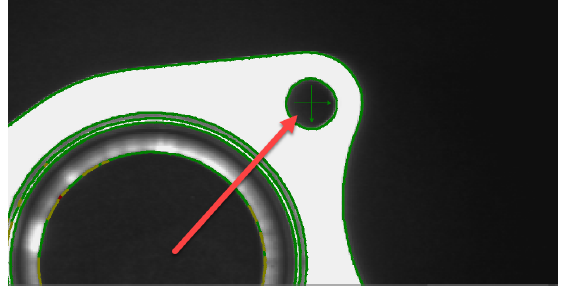
- Write a simple vision job to locate the feature starting with the template job we calibrated. I suggest a simple PatMax pattern. Now move the tracking cross hairs to an easily identifiable part of your image. It is something that we can gauge how accurate our calibration is. Save this job as a new name, you can put a number in front and TEST after.
- Store the robot position in a job. Go to the MS2D pendant application and go to the RESULTS tab. Here you need to assign a position variable the results will be sent to. Also choose the tool you will be programming with (the pointer TCP) and the number of the Calibration UF that you created on the grid. Add these and SAVE the results.
- In the robot job add in a SETJOB macro job and enter the camera number and the number you named the camera job.
- After that add in an INSPECT macro job. Set this up to the appropriate camera.
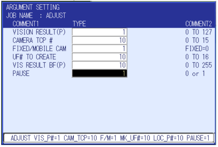
- Now we need to insert the ADJUST macro job. This job will take the camera data and create a UF that can be used on a relative job, and a BUSER which gives us the camera results relative to the robots’ base frame. This can be used for advanced applications. I have setup mock arguments in the picture below. Please be sure to add in the appropriate settings such as camera TCP and UF to create, be sure to set to a MOBILE camera.
- Set the camera online and run the test job making sure to start at the top so you run the SETJOB, INSPECT, and ADJUST job.
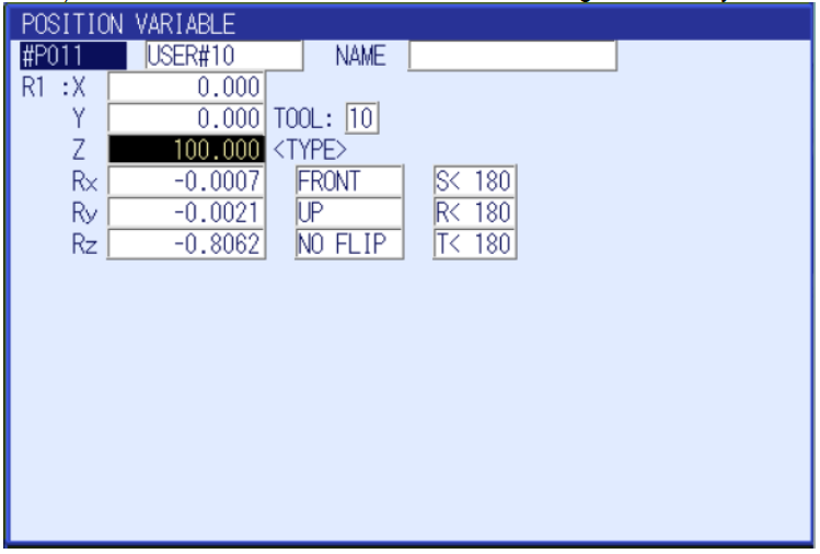
- If you got a good image you should have ran until the ADJUST macro job. In this example I created UF 10. Make sure the pointer TCP is the active tool, then create a position variable relative to the user frame you created (in this example it would be user frame 10.) Set the X and Y elements to 0 and add in a Z height to ensure you do not crash the robot.
- If you forward to this position variable it should take you pointer TCP above the feature you put the cross hairs on. You can move Z- and the pointer should touch that spot. If not go back and complete the calibration again checking pointer TCP and the calibration UF. If it does move to the next step.
- Now you need to move the part linearly and run the job again, you should still be able to move the robot to the feature you placed the cross hairs on when you perform the steps in 3.1.22 and 3.1.23. If not go back and complete the calibration again making sure to check pointer TCP and calibration user frame. If this tracked correctly move to the next step.
- Now you need to rotate the part. Run the job again and you should be able to go to the feature that you placed the cross hairs on when you perform steps 3.1.22 and 3.1.23. If not go back and complete the calibration again making sure to check pointer TCP and calibration user frame. If this was successful, then you now have a correctly calibrated camera.
Comments
0 comments
Please sign in to leave a comment.