Scope and Purpose
This document defines the procedure for the setup of the MS2D option with a stationary camera. If you have a robot mounted camera, please refer to the "Mobile Camera setup with MotoSight2D" article.
Software Requirements
- Software version: Any current MS2D application
- Ladder modification - No
Installation Procedure
- Start off with a properly taught TCP with a pointer affixed to the tooling. Please use the 5-point calibration method and test for a proper roll about. This needs to be as good as possible; this will be used to teach user frames and accurate tool data is required for proper results.
- Prepare the area for calibration. You will need a part or a test part to teach the camera to, a calibration grid from the Cognex Insight Explorer, any lens and lighting that will be used.
- First connect to the camera, you can this with your laptop and Cognex Insight Explorer. Once connected put the camera offline and load the appropriate MS2D template job. The correct template can be found using the text file included with the system, it is based off camera firmware version. If you have MS2D 5.4.2 or above use one of the templates with 1 at the end, these templates maximize processing time but are not compatible with MS2D versions lower than 5.4.2.
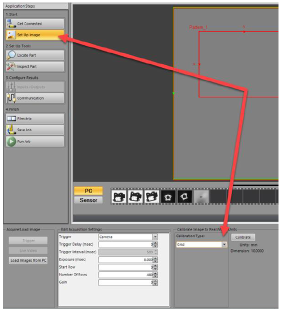
- With the correct MS2D template job loaded into the camera go into “Set Up Image” in Cognex Insight Explorer. Then choose “Grid” under the calibration type and click “Calibrate”.
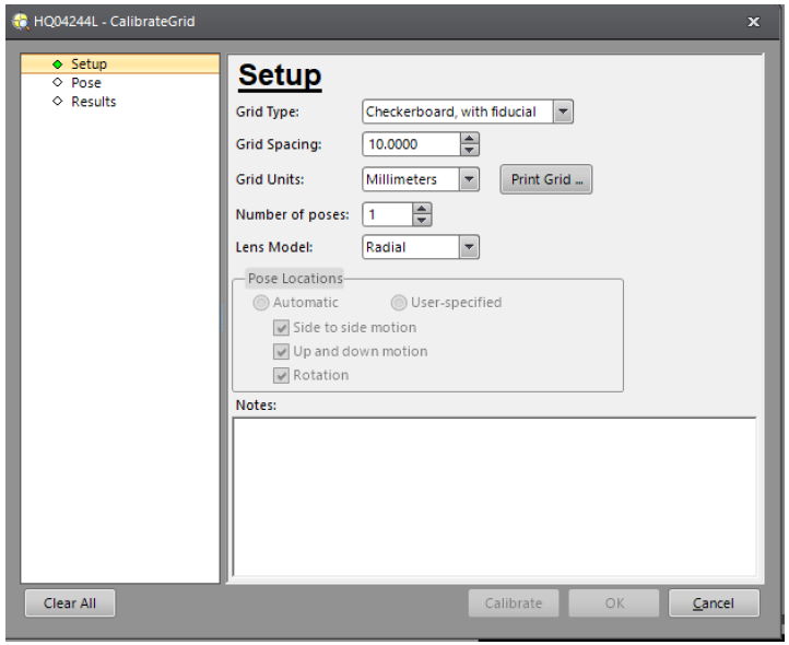
- The Setup calibration pop up will open. This is where we will setup the calibration grid we want to use. You will want to choose the “Checkerboard, with fiducial”, and you will need to select your grid spacing. The grid spacing should be chosen based on your application, Field of View (FOV), and camera resolution. Each square on the grid should be at least 15 pixels wide for the camera. Once this is completed you will need to print the grid. The goal is to fill the FOV if possible, this will assist the calibration and the filters such as Transform.
- Once the grid has been printed, measure the squares to ensure the requested size is the actual size of the grid squares. You will want to mount this under the camera and secure it so that it will not move. It is recommended that you set the grid to the same height as the part. Since the camera is 2D the plane on which the user frame is taught will become the Z 0 height of the results. Here you will want to adjust the lighting and focus to give you the sharpest image you can achieve. I like to zoom in between two squares on the grid when adjusting. This will allow you to adjust so you get the sharpest image between the light and dark transitions.
- If you are not in the calibration set, go back to this screen. Ensure that checkerboard with fiducial and the correct grid spacing are selected. Click “OK” and capture a new image for calibration. If the calibration area is outside the FOV move this in as well. Click on “Calibrate”. You are looking to find between 300-600 intersection points. Once you get a good calibrate save the template job. This can be used to start a new camera job that will already have the calibration completed.
- The next step is to teach a user frame on the calibration grid to give the robot a point of origin in relation to the data coming back from the camera. You will need a pointer attached to the robot or your End of Arm Tooling (EOAT). You need to perform the 5-step calibration to define the pointer’s TCP. This TCP calibration needs to be as good as you can get it, as it will be used to define the calibration user frame and is required for proper operation.
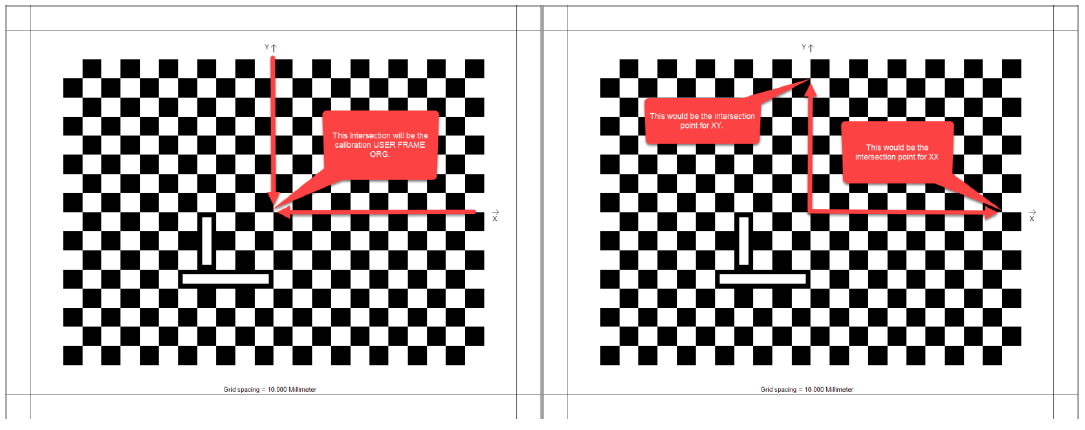
- You will need to select the pointer TCP as your active tool to teach the user frame with. This will be the camera calibration frame, and the data from the camera will be relative to this frame. This will need to be taught as accurately as possible as this will influence the accuracy of the data coming back to the controller. You will teach the ORG at the grid intersection of the X and Y plane. Then teach the XX point on the X plane and the XY on the Y plane.
- Now that the camera calibration and calibration user frame are taught, the calibration can be tested. Ensure the calibration is tested before moving forward as it will need to be performed again if the results are not as needed.
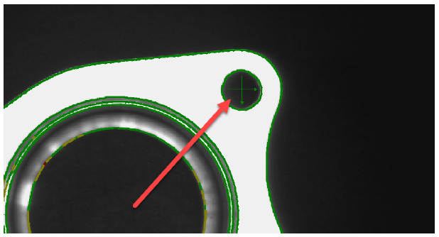
- You can remove the calibration grid or cover it up for the test. Once the grid is removed or covered, place a part or object in the FOV for testing. You will want to start with the calibrated MS2D template as a camera job, and then perform a “SAVE AS” to copy the template to another name. MS2D uses integer values to set jobs in the camera, so an integer needs to precede any other name. I recommend using a number in front and TEST after. Create a simple vision job, I recommend using a simple PatMax pattern for this step. Once the search area and model have been defined, move the tracking cross hairs to an easily identifiable part of the object. This will be used to gauge the accuracy of the calibration. Once this is done save the new camera job.
- With the TEST job as the active camera job, place the camera ONLINE and log out of Insight Explorer. Open the MS2D pendant application on the robot pendant. Go to the RESULTS tab of the application, it is here we assign the camera results to the robot. For a PatMax pattern we have a location result, and a pass/fail result. Go to the TOOL drop down and select the tool that will be used in the vision job, for the test we will choose the pointer TCP tool number. The PVAR User Frame (UF) will be the calibration frame that was taught in 3.1.9. Once these are set choose LOCATION tag and select a position variable to store the data from the camera in and press the two arrows to store this in the assignment list. Next select the PASS tag and select a byte variable to store the pass/fail status in. Once these are all set, press SAVE and then RETURN.
- Now we have the camera and robot calibrated, and the results of our test job assigned to variables in the pendant application. We now need to create a job on the robot to command the camera to capture an image, and to receive the results. Create a test job on the controller, with a R1 as the control group. You will need a SET_JOB, INSPECT, and ADJUST macro job with a small timer between each one.
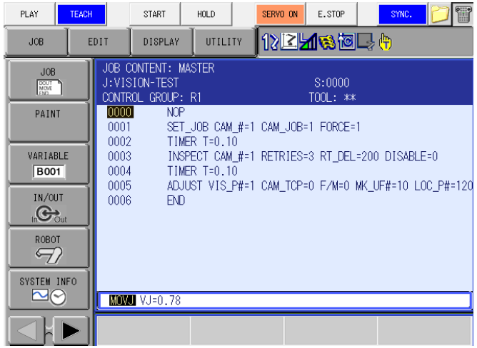
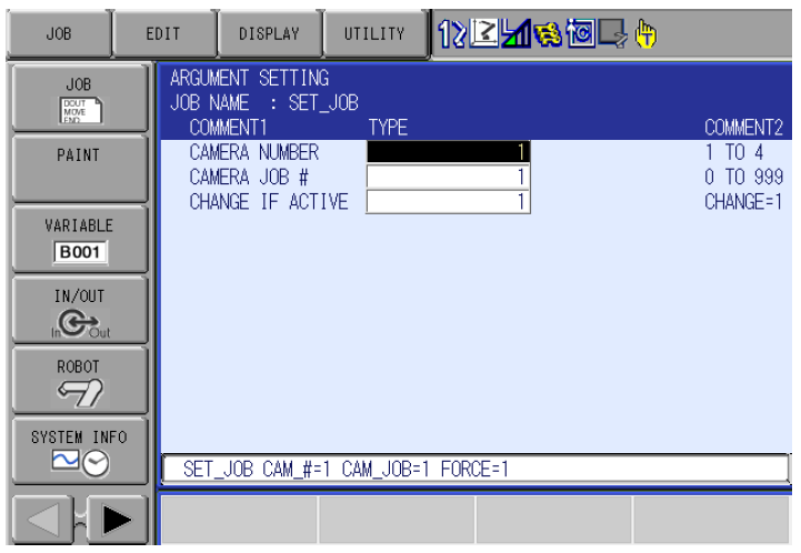
- The SET_JOB macro will be the macro job that will call the desired camera job. You will need to specify the camera number. Up to four can be controlled by a controller. The camera job # is how you will call the desired camera job; this is the reason we have an integer at the beginning of the camera job name. CHANGE IF ACTIVE decides if you wish to force the camera to reload the job if it is already active.
- The INSPECT macro job will be used to trigger the camera. Choose the camera number, the number of retries of the inspection, and the retry delay. The alarm setting will depend on the expected job behavior. When set to a 0 the controller will execute an alarm if there is a failed inspection, stopping the robot and job until there is operator intervention. When you set this to a 1, there is no alarm on image acquisition, and you will need to monitor the Pass/Fail bit setup in the RESULTS tab of step 13.
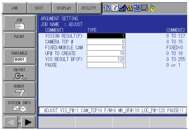
- The ADJUST macro job will be used to take the results from the camera, and turn them into a user frame, and or a BUSER. The standard way to program with vision would be to take the results of the camera and create a user frame with the crosshair from the camera as the origin of the frame. The robot job with the work would be relative to the created UF, and once the user frame is updated the job would update as well. The first argument is the location of the RESULT from the inspection. This is the position variable you choose in the pendant application to assign the results of the camera to. The camera TCP and FIXED/MOBILE CAM arguments will be left at 0 since this is a stationary camera. UF# TO CREATE will create a user frame with the results from the camera. Ensure you choose a different frame # than your calibration frame! The VIS RESULT BF(P) is what we refer to as the BUSER. This is the location of the origin of the crosshairs in the robot’s base frame. This can be used for several things such as checking our calibration, and advanced vision programming. The PAUSE argument will pause the ADJUST job before it ends, this is useful when setting up a vision job and can be turned off for production.
- Once the robot is setup and the macro job arguments are set, you can run the job from the top line. You should have a job that has had a successful inspection, and now either at the end of the job, or at the pause in the ADJUST job. There are a few ways to check the results of the inspection. If the calibration frame was taught at the same height as the part, you can use the easiest way which is to forward to the ORG of the UF that was created in the ADJUST job. Ensure the tool the UF was created with matches the tool that your pointer is setup for, this is set in the RESULTS tab of the pendant application. If you did not teach the calibration frame at the same height as the part, you can add some height to the Z element of the BUSER created in the ADJUST job. You can also create a position variable relative to the user frame created in the ADJUST macro. Move the pointer above the part and enter that position into the position variable. Zero out the X, and the Y elements and place a number in the Z that will allow you to not crash into the part. Remember, the 0 Z height of the created user frame is at the location you taught the calibration frame, so ensure you take the height of the part into consideration.
- You should have the robot pointer at the same location as the crosshairs that were setup in the camera job via Cognex Insight Explorer. If not, check the settings. If all settings are correct, you will need to redo the calibration. Ensure that your pointer TCP has a tight roll about before recalibrating. If the pointer is at the location, continue.
- Now we need to test the calibration against a moving part. Move the part used linearly without adding rotation. Run the job again, and check that the pointer is going to the desired location. If not, check your settings and recalibrate. If the test is passed, continue.
- The last tests we need to do are movement and rotation. This is generally where issues with the calibration become evident (due to the calculations for rotation.) Move the part and rotate it within the rotation allowance that was setup for the pattern tool in Insight Explorer. Run the job and forward to the point. If the pointer forwards to the desired location, you successfully have setup and calibrated the camera and the robot. If the robot does not go to the correct position, you will need to start the calibration again. Ensure the TCP roll about is tight, and that the points taught for the calibration frame are as exact as you can get them. Also ensure the calibration grid is not able to move. If so, the calibration will need to be restarted as well.
Comments
0 comments
Please sign in to leave a comment.