Introduction
We have been asked, “Is it possible to send an output signal while the robot is moving, or do you have to wait until a move is complete?” This document will discuss five methods to send output during a move.
Method 1: I/O Output Timing Control Function
You can send an output signal based on time or distance relative to the move command (See I/O Output Timing Control Function for YRC1000, but also available on DX200). This method uses additional tags on the MOV command to do a DOUT or PULSE based on the distance (ADJD=) or time (ADJT=) tag.
MOVL +DOUT #OT(1) ON ADJD=-10 would raise #OT(1) 10.0 mm before the destination point was reached.
MOVL +DOUT #OT(1) ON ADJT=-1 would raise #OT(1) 1 second before the destination point was reached.
Method 2: NWAIT
Use the NWAIT tag on the move to allow execution of the job to continue (up to the next MOV) while the current MOV completes. After the MOV has started, you can evaluate conditions and send the output accordingly. Example:
0002 MOVL V=138 NWAIT
0003 DOUT #OT(1)
0004 SET I099 0
0005 SET D015 20000
0006 CLEAR R000 ALL
0007 MOVL V=276
In the above example, the MOVL on line 2 would be started and lines 3 to 6 would immediately be processed while the robot moves to the position indicated in line 2. NOTE: Line 7 would not be started until the move in line 2 is completed.
Method 3: Concurrent I/O
Concurrent I/O – ladder updates can send a signal based on other signals and / or timers independent of motion. The CIO ladder is scanned and processed constantly in the background while jobs are running.
Method 4: Parallel Jobs or a System Job
Parallel Jobs or a System Job – can be running while the job doing the move operates. The background job can evaluate conditions and send the output accordingly while the MOV occurs.
Method 5: Use Cubic Interference Signals in the CIO
Another method is to define robot interference areas to raise a signal as the Tool Center Point (TCP) passes through the area. In the Concurrent I/O Ladder, the Specific Output signals for cube interference can then be mapped to other output signals to turn on lights, communicate to a PLC, etc.
The example below shows three interference areas (the purple planes) that were defined. Watch the signals go on and off in the I/O Monitor window on the left as the robot TCP passes through them.
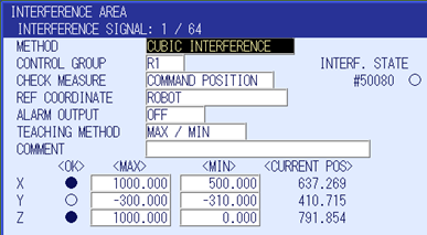
The graphic below shows one of the Interference Areas (the leftmost purple plane) defined for this demonstration.
Comments
0 comments
Please sign in to leave a comment.