INTRODUCTION
The following is a guideline which provides real world advise on the functionality of the relative job software feature.
ADDITIONAL RESOURCES
| EXTERNAL DOCUMENT RESOURCES |
| DX100 relative job instruction manual |
| DX200 relative job instruction manual |
| YRC1000 relative job instruction manual |
| YRC1000micro relative job instruction manual |
| KNOWLEDGEBASE ARTICLES |
PARAMETER REFINEMENT
| PARAMETER | VALUE | DESCRIPTION |
| S2C430 | 0 | Previous step regarded (constant B-axis sign) |
| S2C430 | 1 | Type regarded |
| S2C430 | 2 |
Previous step regarded (minimum R-axis motion) |
| S2C430 | 4 |
Previous step regarded (minimum R-axis motion) + pulse limit avoidance |
** Please note that not all values are available across all controller types. Please reference the relative job manual specific to your controller for available parameter types as well as additional descriptive information.
JOB TYPES
A Yaskawa robot features two different modes in which you can program your robot. The two modes are what we call STANDARD job and RELATIVE job. Each mode essentially refers to the way a position is stored within a job. Standard job references encoder values while relative job references cartesian data.
STANDARD JOB
While this article focus primarily on the potential of relative job, it is of benefit to have a quick understanding on the term "standard job". By default, most robot jobs are automatically created as standard job. You can verify this by looking at the job header.
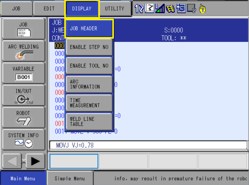
1. While displaying your job, select the DISPLAY menu from the upper menu bar and select JOB HEADER
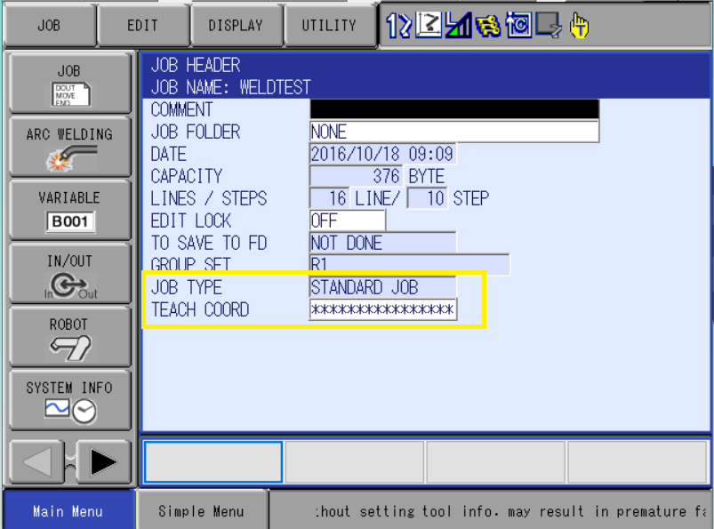
2. The field of "JOB TYPE" will tell you if it's standard or relative job type. Also note that the field "TEACH COORDINATE" is not specified. This is because with standard job type, you do not have any options to choose from. It is always encoder values.
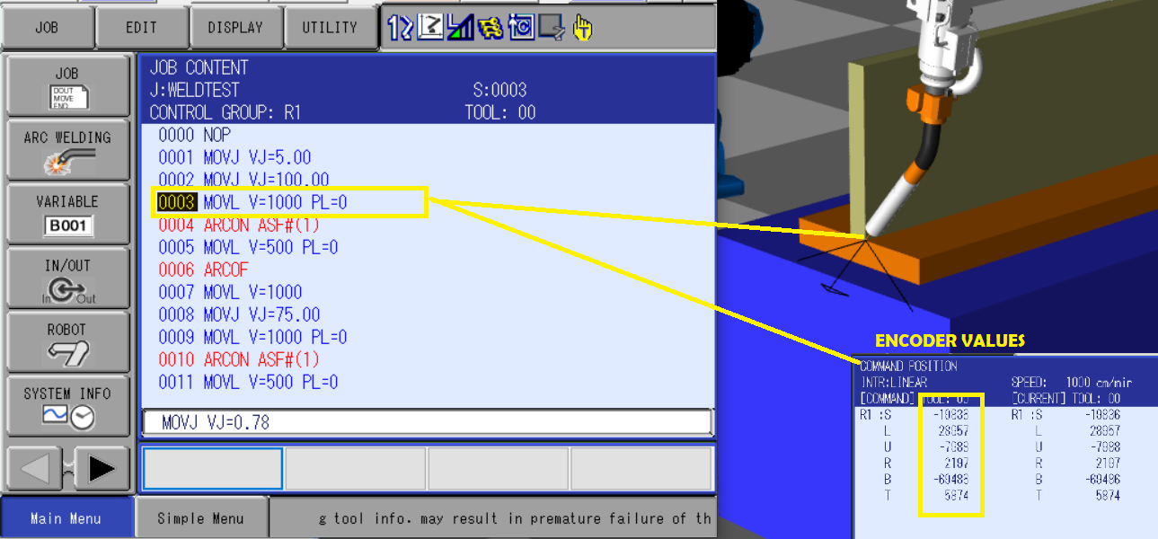
Now... What exactly does standard job mean? Well.... when you record the robots position within a program, the point in space that is registered is compromised of the encoder values for each motor. There is no X,Y,Z, Rx, Ry, Rz values. In the photo below, you will see that the stored data is all encoder values for each joint.
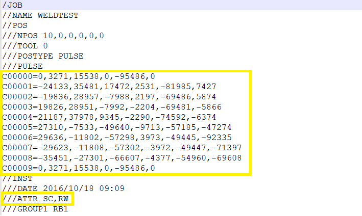
To further your knowledge and reinforce the idea that encoder values are stored within a standard job, you can save the program to your USB drive and examine it offline. Please note in the photo below that the Cxxxx values represent the encoder data for each motor. Additionally, note that the job attributes "ATTR" value does not specify relative job.
As you playback your robot job, the servo system will drive the motors to the stored encoder values. There is no bearing on other factors such as tool data or referenced cartesian frames.
Now... Consider a welding application in which a torch gets bent.
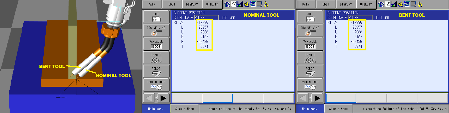
If we compared both scenarios, you can see that the bent tool has the wire tip out of position yet when you compare the current position of the robot, the encoders are all at the same count.
A savvy user may update the robot's tool file afterwards to reflect the fact the torch is no longer at a 45 degree angle... however, because the positional data is stored in encoder counts, subsequent execution of the program will still return the robot to the same encoder positions.... As a result, the wire tip will still be out of position even though you have updated the tool file.
Let us now explore the potential of relative job.
RELATIVE JOB
On the outside, a relative job program looks identical when compared to a standard job. Most users will be none the wiser. However, with relative job, the positional data stored within your program is registered in cartesian co-ordinates. Put differently, instead of storing encoder values, the program is instead recording the X, Y, Z, Rx, Ry, Rz location in space. Along with the location in space, tool information, frame type and robot configuration is also registered.
Let's take a look again at our sample welding application. The points in space remains unchanged, however with relative job, the cartesian co-ordinates have been stored.
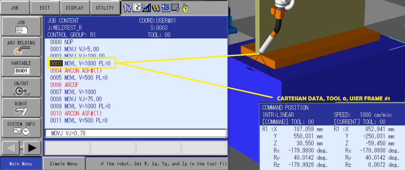
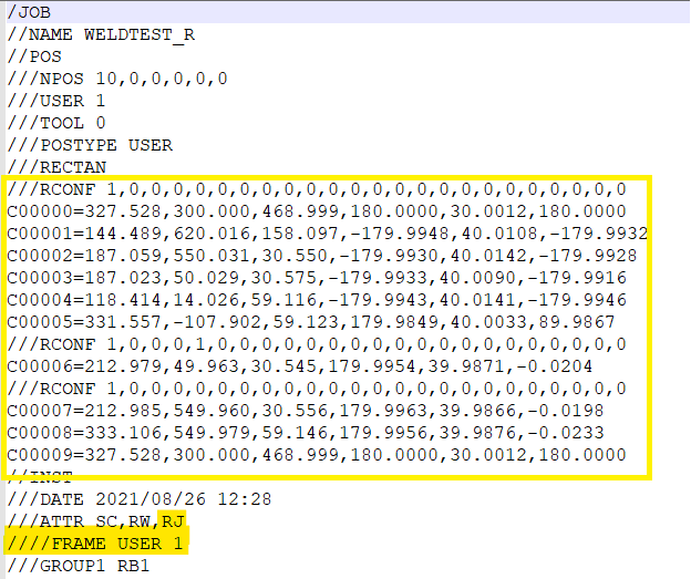
And once again, if we examine the data offline on your computer, you will see that the stored positional information is specified in decimal values + degrees of rotation in place of encoder counts. Our job attributes also specify the frame number for the program.
The attribute of "RJ" indicates it is a relative job.
Now... as your robot is playing back the points, it is going to bring the tool center point to the location in space that was recorded. Using our welding example, let's say that the wire tip was recorded at X=10, Y=10, Z=10. Every subsequent playback will return that wire tip to the same X=10, Y=10, Z=10 location in space.
Updating Tool Data and it's Impact on Relative Job
Now let's say a crash has occurred... Our robot program will still bring the tool center point back to X=10, Y=10, Z=10 however in this case, the wire tip will no longer be in the center of the weld joint. This is because the actual wire tip location no longer matches the tool center point specified within the system.
With relative job, we have the ability to update the robot tool information and consequently, the updated tool center point will be returned to X=10, Y=10, Z=10. Essentially what's happened is you have "touched up" your points by updating only your tool file! This is the founding principle in which our ToolSight product is based upon.
Updating Frame Data and it's Impact on Relative Job
I sometimes like to relate the word "user frame" with the word "starting point"... Essentially, I want you to think of your user frame as a starting point that also provides direction. When you move your user-frame, you are essentially moving your starting point and from the robot perspective.... your physical location in space will also move.
Essentially, you can fine tune the user frame location in space and you will observe that your robot points also move around. (Because you have moved your starting point)
Application Examples with Relative Job
- Offline programming with MotoSIM or other 3rd party software will almost always generate data in relative job format.
- Vision programs are often created with relative job. A robot's program is made "relative" to the camera which makes for a clean and user friendly way to quickly develop vision jobs. (Using my starting point analogy.... the vision data becomes your starting point)
- A welding program is made "relative" to it's tool data resulting in an easy way to touch up your points by ensuring tool center point data is always accurate.
- A robot program can be attached to it's fixture so that the fixture can be shared across multiple
work cells. This can minimize programming time across multiple machines... Simply take the job from machine A, copy it to machine B while updating tool center point and frame data accordingly.
Converting a Standard Job into Relative Job (or vice versa)
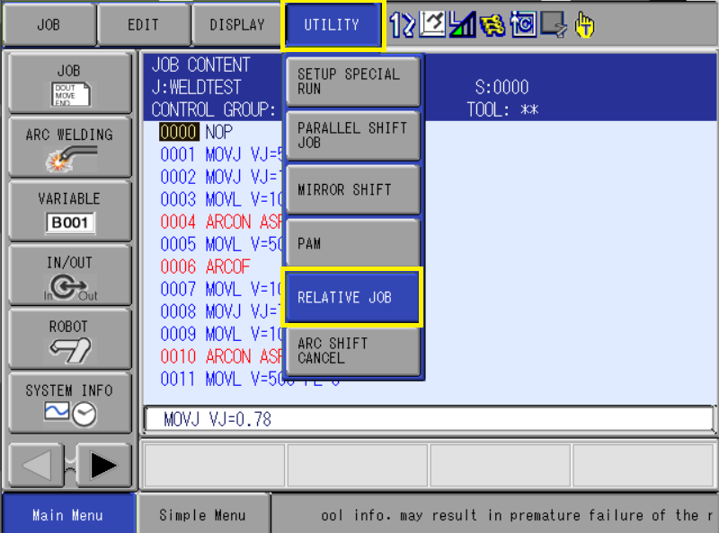
1. Start by displaying your robot program
2. Select the UTILITY menu from the upper menu bar and you will see a RELATIVE JOB option listed.
3. Pick the SOURCE job you wish to use for conversion
4. Specify the frame you wish to "attach" your program to. (In our above welding example, user frame #1 was taught on the welding fixture)
5. A DESTINATION job is optional. If left blank, it will overwrite the source job.
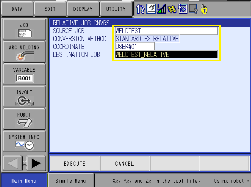
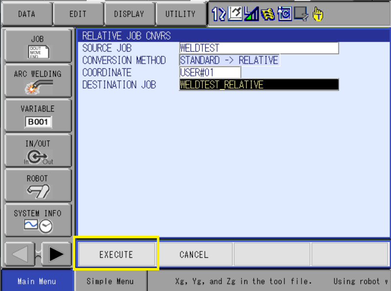
6. Press EXECUTE when ready to start the conversion process.
Comments
0 comments
Please sign in to leave a comment.