INTRODUCTION
A Yaskawa robot controller has the ability to provide a large amount of information. Depending on your application, it is sometimes beneficial to collect current position, speed and/or torque values from teh robot. Sending this information is possible and can be done in a few ways. This article will mainly focus on sending the information to a PLC where a protocol such as Ethernet/IP, ProfiNET, DeviceNET, etc... is used as a communication method. Achieving this task typically involves 2 steps.
** Please note that not all parameters are available across all controller types. Please reference the controller specific manuals or reach out to Yaskawa tech support for more guidance. **
ADDITIONAL RESOURCES
| EXTERNAL DOCUMENT RESOURCES |
| DX100 Operators Manual |
| DX200 Operators Manual |
| YRC1000 Operators Manual |
| YRC1000micro Operators Manual |
STEP #1: PARAMETER SETTING
By setting specific robot parameters, you can populate various registers with the information you require for your application. You must first understand which type of information you wish to send and based on your controller revision, your options will vary slightly. The below are some examples of information type that customers often wish to send:
- Current position of the robot in cartesian, base coordinates. (X, Y, Z, Rx, Ry, Rz)
- Current position of the robot in encoder pulse counts (S, L, U, R, B, T)
- Manipulator TCP speed
- Manipulator each axis speed
- Manipulator torque percentage
The PDF's attached to this article will outline specific guidance for each controller type. Regardless of which data type you are in need of, each have similarities.
- Set parameter to enable the desired function
- Set parameter that points to an available M-register for data storage
- Set parameter to determine the I/O size required. This is typically 2 bytes or 4 bytes in size
An important point to note is that the M-register number you specify is a "starting point". Let's say for example that we want to get the robot current position and I specify M001 as my register starting point.
M001 = X value
M002 = Y value
....
M005 = Ry value
M006 = Rz value
STEP #2: CONCURRENT I/O (LADDER LOGIC) MODIFICATION
This is the more complicated step. It requires the end-user be familiar and knowledgeable with our internal ladder logic system. The goal is to "transfer" the M-register to the PLC over the desired communication method. This article assumes the user is already familiar with our ladder logic.
Before you continue, ensure that you have determined the starting external output you wish to use. For this example, let's assume:
- Ethernet/IP communication is used
- Ethernet/IP external I/O allocation uses 20060 for inputs and 30060 for outputs
- Ethernet/IP I/O size is currently set at 32 bytes
- We wish for the current position to be sent to the PLC starting at external output 30080
Based on step #1 from above, I have set the parameters to populate M-register 1 though 6 with each component of the current robot position. I can now begin modifying the robot ladder logic.
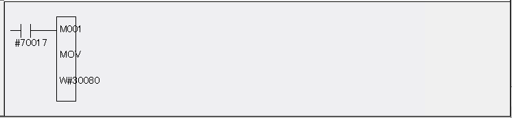
In the photo below, we are using the ladder logic command "MOV" to make the transfer of M001 contents. (our X value) Because the size of an M-register is 2 bytes (1 word) we will specify the starting point for the transfer as W #30080. It is the "W" that indicates "word". If no "W" is specified, then the controller will only transfer 1 byte.
The contact of 70017 is an "always true" bit and will allow the MOV instruction to be processed at every ladder logic scan.
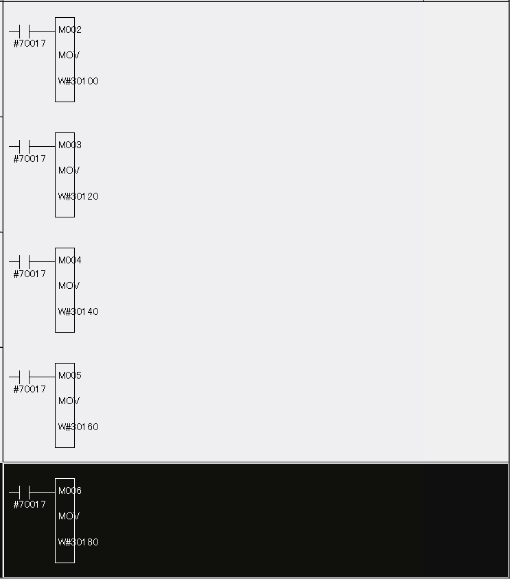
We will copy this same logic 5 more times. Each time, we are changing the M-register value and corresponding external output address accordingly.
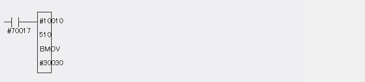
One thing to note is that you may have a compile error. In this example, external output signals 30080 through 30200 are already used within a "batch move" command in the ladder logic. As you will see in the photo below, this "BMOV" command is writing 510 bytes and our desired output range falls within this "BMOV". As a result, you will also need to modify the "BMOV" so that you expose your desire output range 30080 through 30200. As with most PLC logic... you can only write to an output once.
REFRESH RATE
- Depending on your controller, the update interval for this information is between 2ms and 4ms
- This time frame would not include the time it takes to send the information to your PLC. It is mainly the rate at which the M-registers are updated. Communication time is additional to this.
- No additional options are required to purchase for this functionality
ALTERNATIVE OPTION #1 (MOTOPLUS)
Yaskawa robot controllers allow for the development of a MotoPlus application. For those not familiar with MotoPLUS, it gives you the ability to develop an "app" and load it onto the robot CPU for execution. It is similar to how we download "apps" from the "app store" to gain new functionality on our phones. With MotoPlus, you can also capture position, speed and torque. Some highlight points are:
- Update interval is often faster then sending to PLC (ie: < 4ms)
- Data can be sent out on TCP or UDP socket in any format
- Requires development in ansi C to create an executable that runs on the robot controller
- Requires purchase of the MotoPlus SDK
ALTERNATIVE OPTION #2 (HIGH SPEED E-SERVER)
- The timing is not very deterministic. Data can be polled approximately every 20 ms
- Requires development of a PC application that uses UDP socket communication to the robot controller
- No additional controller options need to be purchased
Comments
0 comments
Please sign in to leave a comment.