Introduction
The Working Trace in MotoSim is an extremely useful tool for laying down a weld (for example.) Working Trace Can also be used to show the path of things like 3D printing a house with concrete or dispensing adhesive on car parts. It may also be used in other applications, with the different commands described later in this document.
Setting Up the Working Trace
1. On the Simulation tab, click on the Working Trace icon.
2. After clicking on Working Trace, the Working Trace Manager (1) will open.
3. Next, click on the edit (2) or double click on the highlighted WT1 (3).
4. Doing the previous will open the Working Trace Properties window.
If using a positioner, you will need to make sure the dispensing model is attached to the positioner.
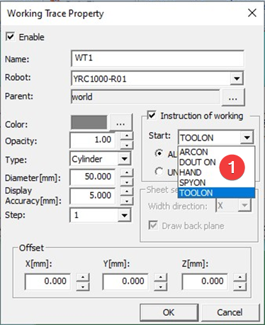
| Click on the square (1)and pick the model from the CAD tree of any model you plan on the work trace to follow. (2) Create a name for you trace model here. To have the trace start and stop, check the box (3) for “Instruction of working”. Just below the instruction of working, you will see a pull down (4) for START. There, you will see Arc On, DOUT On, HAND, Spray on and Tool On. This section (5) defines the model type. If it is a cylinder, line, or sheet. In this section (6), you will define the size of your work trace. In the case here, I am dispensing concrete in a 3D printing application, so it is 50mm diameter. |
When you run the job, and a Tool on is given, then the working trace will start. It will end on Tool off. There are also other commands (1) that you can set to use.
Conclusion
The working trace is a great tool for checking path, tying in welds, or other processes to ensure the correct start and End locations. It also works great when creating a path, like dispensing concrete. To help visualize each path or build an actual model, like a 3D printed house.
Comments
0 comments
Please sign in to leave a comment.