Introduction
This document will help guide you through creating tool interference files. This option is standard on YRC controllers. Additional information on the Tool Interference function can be found in the Arm Interference Check Function Manual and the Functional Safety Function Manual.
Tool interference files give you the ability to model an interference area around your end of arm tooling (EOAT). This is extremely useful as it can enable you to monitor the tool within Functional Safety Unit (FSU) Robot Range files and ensure multiple robots on a single controller include the EOAT in arm interference. If you are using either of these options, without the tool interference file setup the robot will not monitor past the T axis flange of the robot.
Tool interference files give you the ability to use up to 5 cylinders to encompass your tooling. At the end of each cylinder is a sphere, the size of the cylinder is dictated by the radius of the sphere that you enter. Each new cylinder must intersect or connect to at least one other cylinder in the file.
Creating Tool Interference Files
To setup first you need to ensure you are in the correct security level:
- If you do not have FSU, log into MANAGEMENT security level.
- If you do have the FSU, log into SAFETY security level.
The TOOL INTERFERENCE menu can be found under the ROBOT tab on the pendant.
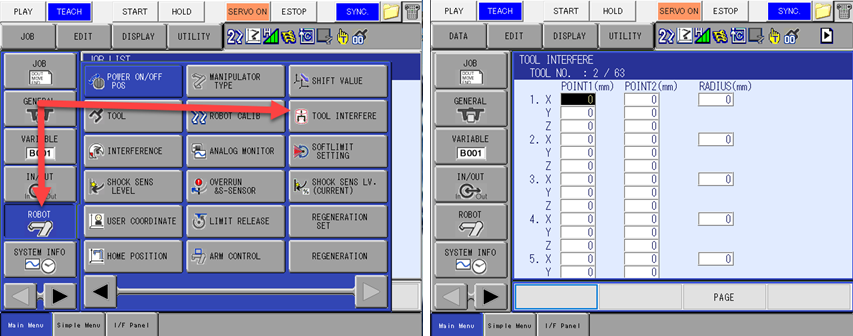
Each interference cylinder will have a start point and an end point, point 1 and point 2. Keep in mind that the X, Y, Z data that is entered is relative to the Tool Frame, not the Base Frame of the robot. The Radius determines the size of the sphere at each end of the cylinder, along with the cylinder size. The definition of your interference file can be done within MotoSim VRC to help see the interference cylinder(s) around the model of your tool. If you do not have MotoSim VRC the YRC controllers also have a 3D Display function that the Tool Interference file can be viewed on, though you will not be able to load your tooling model on the pendant. Information on the 3D Display Function can be found in the 3D Graphic Display Function Manual.
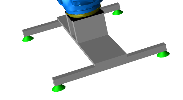
For this example, we will use a simple vacuum gripper attached to the robot. There is more than one way to model this interference area, since there are 4 distinct areas of the gripper, we can make a cylinder for each area.
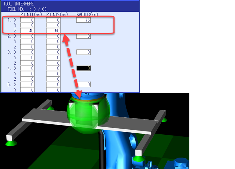
For the first line we will model the section that is attached to the flange of the robot. Since this part of the gripper is centered on the center flange, I entered the following data into the Tool Interference screen. This results in a 10mm line, with a sphere radius of 75mm as can be seen below.
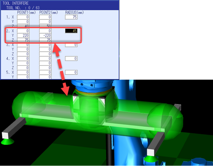
The next model will be for the center support that attaches the suction cup supports on either side. For this we will model the line across the Y plane of the tool frame with a 45m radius. This will create the second line, which intersects with the first and allow us to tie in the suction cup supports.
Next, lines 3 and 4 will be added to encompass the suction cup supports and complete the tool interference model.

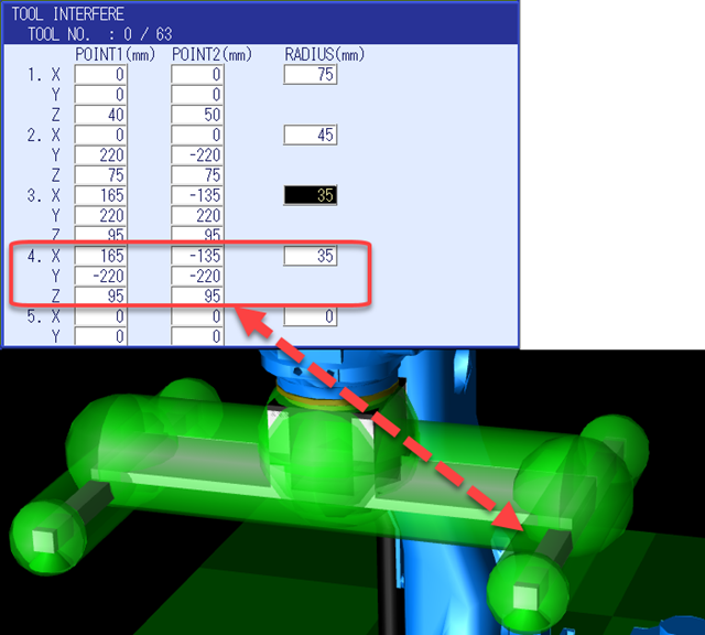
There is now a Tool Interference file created for Tool File 0. Any time Tool File 0 is active, the Tool Interference file will also be active. That means you can model an unloaded gripper and a loaded gripper, or model multiple tools if you have an Automatic Tool Changer (ATC).
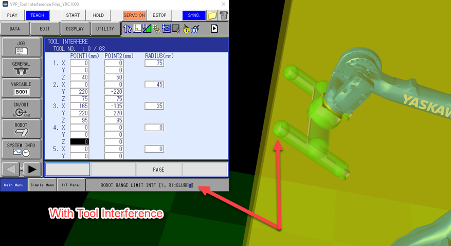
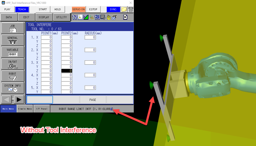
Below is an example of Robot Range Monitoring with and without having setup a Tool Interference File.
Tool Interference stops the robot before the tool can exceed the Robot Range Limit, keeping the entire robot inside the range.
Without a Tool Interference file, the tool can move past the Robot Range Limit before the robot is stopped. This may be a safety concern.
Comments
0 comments
Please sign in to leave a comment.