Introduction
A good tool file ensures path accuracy & longevity of the robot. This document will review the procedure for creating a good tool file definition using 5-Point Calibration and automatically calculating tool weight.
Requirements
- Safety Mode if system has FSU. If not, Management Mode
- S2C431=1 for multi tool
Procedure
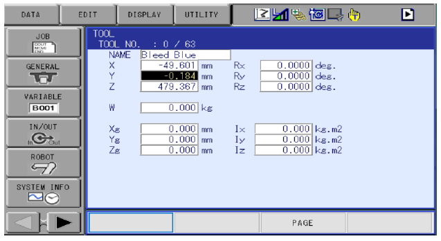
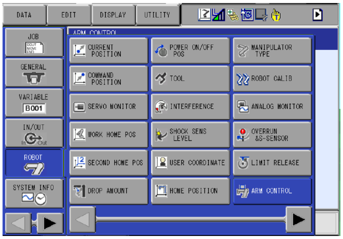
- Navigate to the TOOL screen.
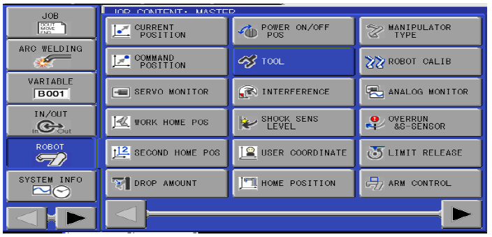
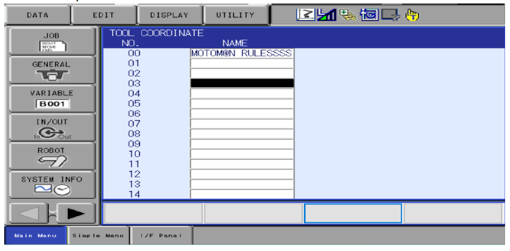
- Select the tool number you want to use. Up to 64 tools are available.
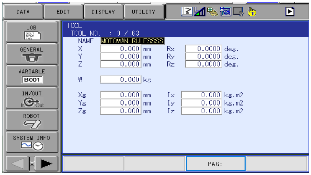
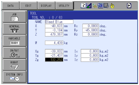
- Tool File values should be all zeros before starting. After performing the 5-point calibration the X, Y, Z values will auto populate.
- Select “UTILITY” then “CALIBRATION” buttons.
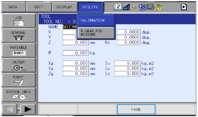
- Next, select which robot you want to perform tool calibration on.
- Select Method
-
- “Coord” calibrates only the coordinates
- “Posture” calibrates only the posture
- "Coord+Posture” calibrates coordinates plus posture
- NOTES:
-
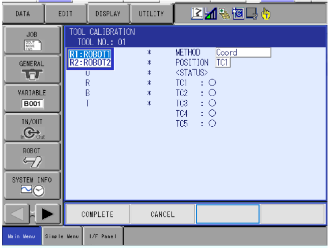
- When performing the 5-point calibration maintain servos through the teaching process.
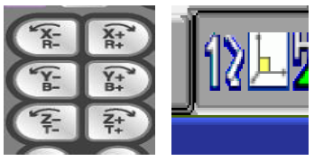
- To record a point press MODIFY ENTER.
- Make sure when recording TC# the appropriate one is selected.
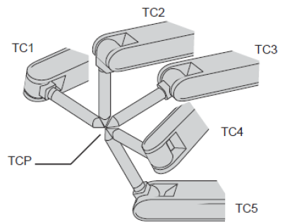
Record points TC1-TC5, the posture of robot should change between points but must maintain same location on the pointer.
- Once points TC1-TC5 have been recorded, select “Complete”.
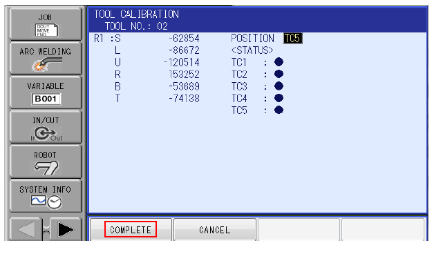
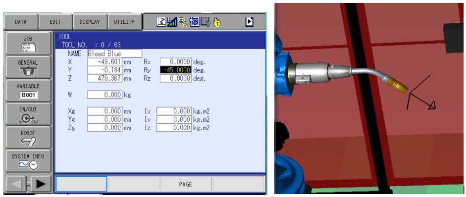
- Verify that X, Y, Z has populated with data. If the system has the FSU feature, you will have to do a Functional Safety Reset in Maintenance mode.
- Using the roll about keys and robot frame coordinate, make sure that the robot rolls about a known location with minimal drift.
- Lastly enter the correct values into RX, RY, RZ to change the tool’s angle of orientation in relation to the operation of tool frame.
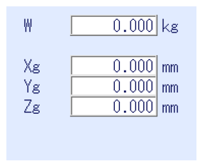
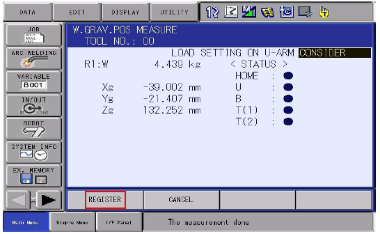
- When performing the auto weight calibration, it populates 2 things:
-
- Weight of the tool (W)
- Center of gravity/mass (Xg, Yg, Zg).
- These measurements control and adjust ACCEL and DECCEL parameters for the robot and affect cycle time and robot speed drastically. It is very important to have good numbers, otherwise damage to robot can occur.
- Depending on the position of the robot this data can fluctuate. The recommended posture of the robot when performing this auto calibration is second home position.
- Before performing auto calibration two values will be configured within the arm control values: S-Axis Payload and U-Axis Payload.
S-axis Payload. If no weight is mounted here, then leave these numbers defaulted to 0.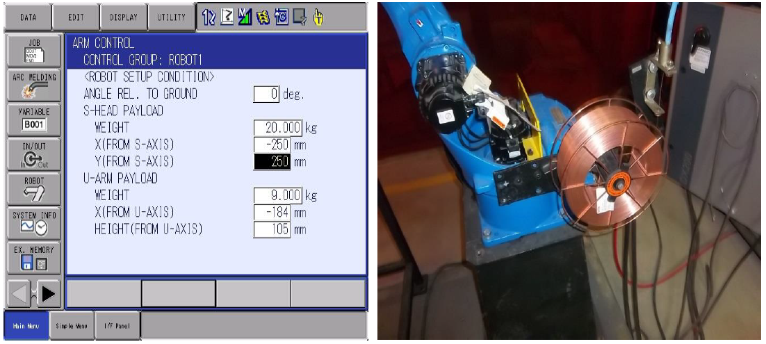
U-axis payload. By default, each robot has a value already in it. Adjust this number accordingly depending what is mounted on the back of this axis.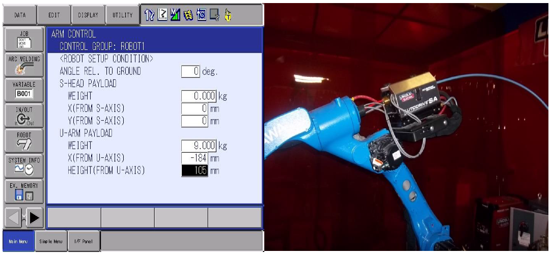
- Navigate back to the tool file and select UTILITY then W.GRAV.POS MEASURE
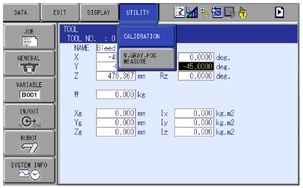
- If you have anything attached to the upper arm select CONSIDER for load setting.
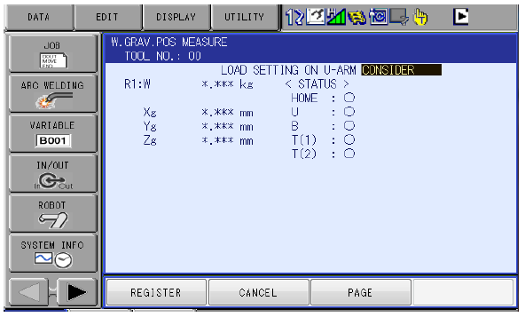
- In teach mode, enable servos, and maintain servo power through this process. Press and hold FWD key on the teach pendant until the robot reaches its calibration home position. Depress the FWD key. Press and hold the FWD key again until the robot stops its calibration routine. Select REGISTER.
- Make sure the correct values from the calibration are within the tool file.
The how to video below covers the weight and gravity calibration for the tool file.
Comments
0 comments
Please sign in to leave a comment.