Introduction
Sometimes it can be difficult trying to “size” a robot to fit an end-of-arm tool. There may be no CAD model, or a person may not be trained to use Yaskawa’s Motosize web tool. However, each robot manual includes a chart that shows the capable mass load based off the tool’s estimated Center of gravity (Cg). This allows for a quick check to help hone in on a target robot model.
6-Axis or 7-Axis Arms
The tool load derating charts are usually found in section 6 of a robot instruction manual…Allowable Wrist Load…Moment Arm Rating. For example, here is a link to the information for a GP25.
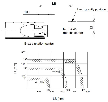 |
Depending on the Load gravity location (Cg) the robot will either be able to carry the rated load or less or non…if the tool Cg is too far from the robot’s flange. Simply measure the LB (factoring in the flange offset) and LT then compare to the chart. The farther from the flange…the less the robot can carry. |
4-Axis Parallel Link Arms
These robots are designed to carry large and heavy tools but if the tool is too long and the Cg is too far from the robot flange…it may be an issue…depending on the tool mass. Like the 6 axis arms, this chart can be found in section 6…Allowable Wrist Loads…Moment Arm Rating.
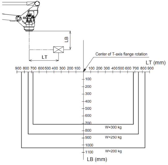 |
Depending on the Cg the robot will either be able to carry the rated load or less or non…if the tool Cg is too far from the robot’s flange. Simply measure the LB and LT then compare to the chart. The farther from the flange…the less the robot can carry. |
Important Notes
These charts do NOT replace Motosize. They are highly simplified and do not account for complex tooling or additional arm loading.
Comments
0 comments
Please sign in to leave a comment.