POWER SOURCE CONDITION FILES
Power Source Condition Files are the interpolation tables that allow the controller to convert absolute welding parameters (amperage and voltage) to analog or digital signals (AWELD and VWELD). Multiple files are pre-defined for different power sources, different shielding gases, and different wire diameters. End users can define “custom” files for specific applications.
Displaying the POWER SOURCE CONDITION FILE
To display the current Power Source Condition File:
1. From the Main Menu, choose Arc Welding.
2. Choose POWER SOURCE COND.
The active Power Source Condition File will be displayed. Welder 1 is used for Robot 1 on all Arc Welding systems. If two welding robots are controlled by the same controller, Welder 2 is assigned to the second robot. If a system is using multiple welders on the same robot (ie twin-wire welding or a tool changer for different torches) the first welding power source will be Welder 1 and the second will be Welder 2. Using the PAGE key provides access to Welder 2. Cursor up or down to show active reference data.
Power Source Condition File description
Each Power Source Condition File contains reference data for 1) the Power Source, 2) Amperage, and 3) Voltage. Each of these sections of the file can be modified to allow information specific to the power source and robot cell. Files that have been pre-defined may be accurate for the cell, or may not be accurate.
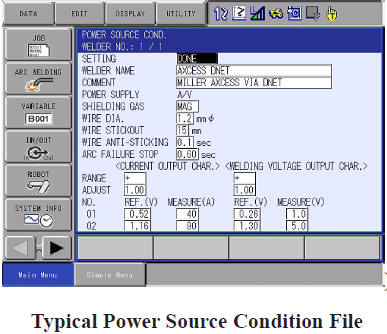
Power Source section
SETTING Done/ Not Done. Indicates that the File is active for use. Must be set to Done to become Active.
POWER SOURCE NAME Used to display a name of the power source, This can be up to 32 characters.
COMM Displays a comment of up to 32 characters.
POWER SUPPLY Specify setting A/V if the welder is a standard power supply. The welding voltage is specified as a constant. Specify setting A/% if the welder is a unified/synergic power supply. The welding voltage is determined by the power source and the V% becomes a voltage trim.
NOTE: This setting can only be changed by “reading” a Maker defined or User defined power source.
SHIELDING GAS Co2 or MAG
WIRE DIA. (0-9.9mm) Specifies the wire diameter.
WIRE STICKOUT (0-99mm) Specifies the length of wire protruding from the torch tip (ESO).
WIRE ANTI-STICKING Specifies the duration of the anti-stick process at the end of welding.
ARC FAILURE STOP (0-2.55sec) Specifies the time between the detection of arc shortage during welding and the stopping of the manipulator movement.
Power Source Condition File (Current)
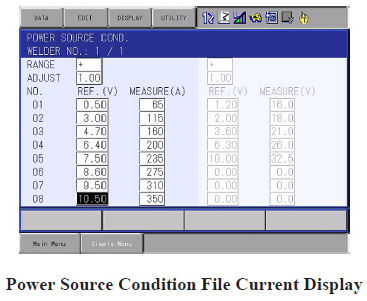
RANGE + or - Indicates the polarity of the reference voltage (AWELD). If the range is positive (between 0 and 14.00 V), ensure RANGE indicates + . If the range is negative (between 0 and -14.00 V), ensure RANGE indicates - .
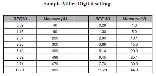
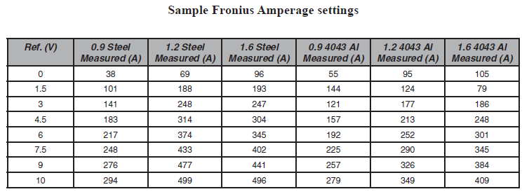
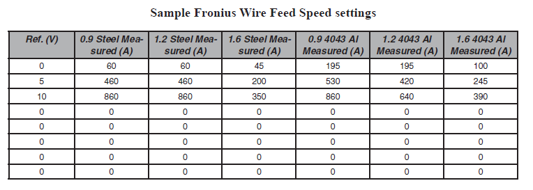
REF.(V) Welding current reference voltage (AWELD values).
MEASURE (A) The wire feed speed or amperage associated with the REF.(V) value.
NOTE: Reference the appropriate manual for REF.(V) and MEASURE(A) settings.
ADJUST A multiplier to adjust the current output. With 1.00 as nominal, .80 to .99 decreases current/wire feed speed, 1.01 to 1.2 increases current/wire feed speed.
NOTE: When using manufacturer supplied values for REF.(V) and MEASURE(A), the ADJUST must be set at 1.00 for accurate results.
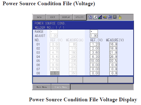
RANGE + or -Indicates the polarity of the reference voltage (VWELD). If the range is positive (between 0 and 14.00 V), ensure RANGE indicates + . If the range is negative (between 0 and -14.00 V), ensure RANGE indicates - .
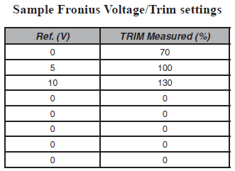
REF.(V) Welding voltage reference voltage (VWELD values).
MEASURE (V) The voltage or trim associated with the REF.(V) value.
NOTE: Reference the appropriate manual for REF.(V) and MEASURE(V) settings.
ADJ A multiplier to adjust the voltage output. With 1.00 as nominal, .80 to .99 decreases voltage, 1.01 to 1.2 increases voltage.
NOTE: When using manufacturer supplied values for REF.(V) and MEASURE(A), the ADJUST must be set at 1.00 for accurate results.
Reading and Selecting Power Source Condition Files
When changes are made to the cell, a different Power Source Condition File may be required. The DX provides “saved” copies of the Power Source Condition Files that may be opened for use. These are selectable from a “Maker” list of 24 files and a “User” list of 64 files.
To read one of the provided files:
1. Choose ARC WELDING.
2. Choose POWER SOURCE COND.
The active Power Source Condition File for Robot 1 will be displayed as Welder 1. If Welder 2 exists, using the Page Key will display Welder 2, etc.
NOTE: When another Power Source Condition File is desired, perform steps 3-5.
3. Choose DATA in the Menu Area.
4. Choose READING.
A list of the 24 preset Power Source CONDITION (maker) files will be displayed. Pressing the page key will display the list for the 64 USER files.
5. Cursor to and SELECT a file to view its reference data.
NOTE: READING a file places the selected file as the Power Source Condition File. If a custom file had been developed and not written to a USER file, all custom data would be lost.
Editing POWER SOURCE CONDITION FILE(S)
When changes are required, the Power Source Condition File is edited. Prior to making changes to this file, ensure that the existing file has been “written” to one of the User Files. Only files that are written are saved for future use. After changes have been made and accuracy confirmed, the new file should be written to one of the User Files.
Editing a Welder Name, Comment, Shielding Gas, Wire Diameter, or Extension
These items are in the files for identification/information purposes only. Changing any these items does not affect the function of the file.
To edit:
1. Display the Power Source Condition File.
2. Cursor down to highlight the desired line and press SELECT.
3. Using the Keyboard, enter the name or information.
4. Press ENTER to place the information in the file.
Editing Power Supply
To change the power supply type, perform the following:
1. In the MENU area, choose READING.
2. In the MAKER list, cursor to the correct power source, verify the POWER, press SELECT. To create a new file, PAGE to the USER list, cursor to a selection with the correct POWER, press SELECT.
Editing Anti-Sticking and Arc Shortage Stop
Changing these timers affects how the arc stops and reacts to loss of arc.
To change wire anti-sticking and arc shortage stop:
1. Display the Power Source Condition File.
2. Cursor down to highlight the desired line and press SELECT.
3. Enter the desired timer setting, press ENTER.
Changing the SETTING to DONE
The Power Source Condition File is not usable until this selection has been made. If the SETTING is NOT-DONE, the controller will alarm when attempting to execute an ARCON instruction.
To make the SETTING DONE:
1. Display the Power Source Condition File.
2. Cursor to SETTING.
3. Press SELECT to toggle to DONE.
NOTE: Any changes made to the Power Source Condition File will cause the SETTING to toggle to NOT-DONE.
Editing POWER SOURCE CONDITION FILES (Current and Voltage)
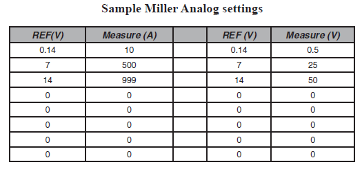
Many Power Source manufacturers provide information concerning the relationship between the analog signal and the actual provided current/wire feed speed or voltage. These settings are installed in the Power Source Condition File.
To edit current or voltage data in the Power Source Condition File:
1. Display the Power Source Condition File.
2. Cursor down to desired line and press Select.
3. Enter the values into the appropriate section of the Power Source Condition File.
4. Repeat Step 2 and 3 until all measured values are entered.
NOTE: A minimum of 3 fields of data are required by the File. Any fields left with “0” in Ref V and “0” in the Measured column will not be used for calculations.
5. Cursor to SETTING NOT DONE and press SELECT to sequence the file to DONE.
Sample welds may be performed using absolute values for current and voltage to ensure accuracy. Perform these welds using the same job modified from analog values to absolute. Use of new undistorted plate material is recommended to ensure consistent temperature and ESO.
Saving the edited data
Unless the Power Source Condition File is written to one of the User Files, it is not saved. READING any of the saved files over-writes the Welder 1 file. When accurate information has been developed, it should be written to one of the User Files to ensure availability at a later time.
To write the information to a User file:
1. With the Welder X File displayed, choose DATA in the Menu Area.
2. Choose WRITING.
3. Cursor to the User File where the information will be written, and press SELECT.
4. In the “WRITE DATA?” box, choose YES.
Comments
0 comments
Please sign in to leave a comment.