WEAVING CONDITION FILES
The DX100 supports 255 weave files that can be setup up with various patterns. The direction of the patterns are based on the default coordinate system as described below or on taught reference points.
Displaying & Editing WEAVE Files
To display and edit WEAVING CONDITION files, perform the following:
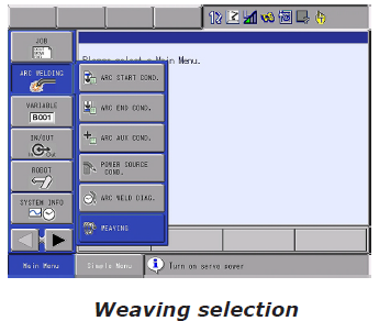
1. Choose ARC WELDING.
2. Choose WEAVING.
3. Press the page key to access files 1-255.
or
Press PAGE, enter the desired number, and press ENTER.
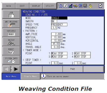
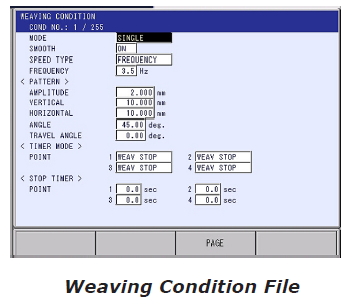
WEAVING CONDITION FILE
WEAVING COND NO.
This displays the file number (1-255). Files are selectable by using the Page/Shift Page keys or by using the Page button for directly choosing the file number. The instruction WVON WEV#(X) can also be opened with the Direct Open key.
MODE
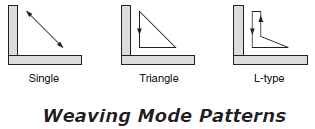
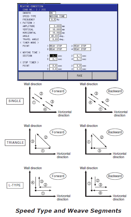
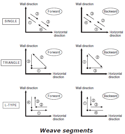
There are three weaving oscillation modes: Single, Triangular, L-type.
Single, Triangular, L-type
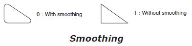
SMOOTH
Each mode can be specified to use or not use smoothing, or corner rounding.
SPEED TYPE
This selection identifies how the weaving speed is defined. If FREQUENCY is set, then the weave speed is defined in cycles per second (Hz). If MOVING TIME is set, then the weave speed is defined as absolute time for each segment of the weave pattern.
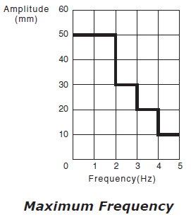
FREQUENCY
This setting is only active when SPEED has been set to FREQUENCY. The maximum frequency is determined by the amplitude.
PATTERN
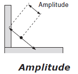
Based on the Mode selection, the Pattern elements define how the weave will operate. Amplitude
When Single Mode has been selected, the Amplitude value is half the width of the weave. This defines the movement of the TCP, not the width of the weld bead. Selections for Smooth and Frequency also affect the total bead width.
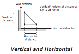
Vertical and Horizontal
When the Mode is specified as either L or Triangle, the size of the Fillet legs are specified.
ANGLE
The Angle element is used differently when using different Modes of weaving.
Single
When a Single Mode is specified, the Angle is the offset from a flat or horizontal weave. A “0” value would give a flat weave, “30” would be appropriate for a lap joint, and “45” would be appropriate for a T joint.
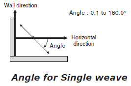
This angle is relative to the Robot Frame by default, but may be changed through the use of Reference Points.
L and Triangle
When either an L or Triangle mode is specified, the Angle becomes the included angle between the Vertical and Horizontal legs.
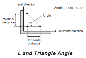
A value of “90” would be used for a 90 deg Tee joint.
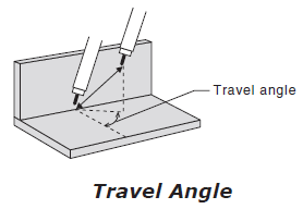
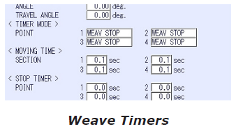
TRAVEL ANGLE
Any MODE may use a Travel angle. This will advance the upper or lower side of the weave ahead of the other. For a “push” angle use -0.1 to -90.0 or for a “drag” angle use 0.1 to 90.0.
TIMER (Mode Selection)
Defining a Timer at the end of an individual segment of weave causes a pause in motion. This may be set as a Weave Stop where the weaving stops but the robot linear motion continues, or a Robot Stop where both weaving motion and robot linear motion stop.
MOVING TIME
If SPEED TYPE is set for MOVING TIME, then the moving time for each segment must be specified. This section is not available when SPEED TYPE is set for FREQUENCY.
STOP TIMER
This identifies the Timer amount at the end of each segment. When set at “0,” no delay occurs at the end of the segment. The Stop Timer relates directly to Timer (Mode Selection).
Programming the WVON Instruction
The Weave instruction can be programmed either with reference to a Weave File or using in-line tags. With 255 Weave Files, an individual file can be established for specific conditions. The use of in-line tags limits the weave to Single only, but allows the variability of having a weave condition for each weld joint, or referencing variables for amplitude, frequency, angle, and direction information.
Programming a WVON WEV#(X)
To program the WVON instruction complete the following:
1. Open the INFORM LIST and choose DEVICE.
2. Choose WVON.
3. Cursor in the Edit line to the File number and press SELECT.
4. Enter the desired file number and press ENTER.
If a different direction is desired:
5 Cursor to the WVON instruction, press SELECT to enter the Detail edit screen.
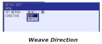
6. Cursor to the Direction element and press SELECT.
7. Choose DIR=, enter “0” for normal direction or “1” for reversed direction.
8. Press ENTER/ENTER to accept the Detail Edit and the Edit Buffer line into the job.
Programming a WVON with In-Line tags
To program the WVON instruction complete the following:
1. Open the INFORM LIST and choose DEVICE.
2. Choose WVON.
5 Cursor to the WVON instruction, press SELECT to enter the Detail edit screen.
4. Cursor to WEV#() and press SELECT.
5. Cursor to AMP= and press SELECT.
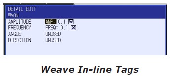
NOTE: WVON with In-Line tags is limited to Single weaves only. With ANGLE set as UNUSED, the weave defaults to 45 deg.
6. Choose and enter the desired elements and values.
7. Press ENTER/ENTER to record the instruction into the job.
Programming the WVOF Instruction
To program the WVOF instruction complete the following:
1. Open the INFORM LIST and choose DEVICE.
2. Choose WVOF.
3. Press ENTER to accept the input buffer line “=>WVOF” into the job.
Default Coordinate System for Weaving
The Wall direction will always default to the Z+ direction of the Robot Frame. The side of the wall that the approach point is programmed determines the default horizontal direction.
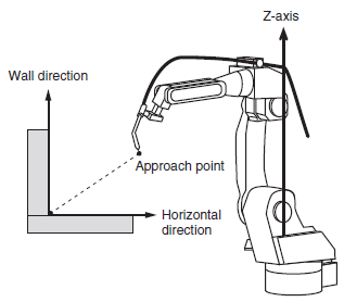
NOTE: Depending on the mounting and shape of the workpiece, the default Basic Coordinate System may not be appropriate, even when the proper direction of the approach point is used. Some situations require Reference Point 1 and/or Reference Point 2 be taught to achieve desired weaving results.
Cases Requiring Reference Points
The registration of Reference Points is necessary whenever the approach point can not be programmed from the proper direction due to positioner obstructions, etc., or the mounting and/or shape of the workpiece is not parallel to the default vertical Wall and/or horizontal direction.
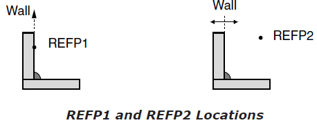
• Reference Point 1 (REFP1) defines the Wall direction. The REFP1 must be programmed on the desired wall surface.
• Reference Point 2 (REFP2) defines the horizontal direction. The REFP2 must be programmed to indicate which side of the wall will be welded. The position of the approach point in the job becomes irrelevant whenever REFP2 is used for determining the side.
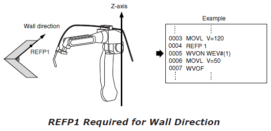
REFP1 should be programmed when the wall direction is not parallel to the Z-axis.
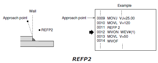
The need for REFP2 occurs when the approach point cannot be programmed at a location where the controller recognizes the correct side of the wall for the desired weave. This is often seen as a “sewing machine” weave movement.
Teaching a Reference Point
To teach a Reference Point, complete the following:
1. Display job content.
2. Cursor to a line above the WVON instruction.
3. Jog the robot’s TCP to the desired reference point location.
4. Press the INSERT key.
5. Press the REF PNT key (the “0” key on the numeric keypad).
6. Cursor to Reference Point number press SELECT, enter the number of the desired Reference Point, and press ENTER.
7. Press ENTER.
NOTE: To move the robot to a taught reference point, put the cursor on the desired REFP line in the job, press and hold the REF PNT key (“0” on the numeric keypad) and then press the FWD key until the robot moves to the reference point’s position.
Modifying REFERENCE POINTS
To Modify a Reference Point complete the following:
1. Cursor to the line of the Reference Point to be modified.
2. Move Robot to the desired position, press the REF PNT key.
3. Enable Servo Power, press the MODIFY key.
4. Press ENTER.
Deleting REFERENCE POINTS
To DELETE a Reference Point complete the following:
1. Cursor to the line of the Reference Point to be deleted.
2. Forward the robot to the REFP.
3. Leaving Servo Power ON, press the DELETE key.
4. Press ENTER.
Prohibiting WEAVE Operation
Weaving may not be desired during FWD or INTERLOCK/ TEST START operation in TEACH or during Playback in CHECK mode operation. It can be prohibited.
To prohibit weaving, perform the following:
1. Set the controller into the desired mode, PLAY or TEACH.
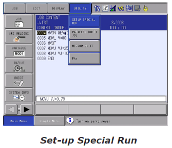
1. From the Job Content screen choose UTILITY in the Menu Area.
2. Choose SET-UP SPECIAL RUN.
3. Cursor to WEAVE PROHIBIT IN TEST-RUN/NEXT (Teach Mode) and make VALID.
or
Cursor to WEAVE PROHIBIT IN CHK-RUN (Play Mode) and make VALID.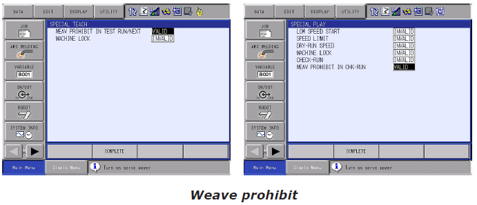
Comments
0 comments
Please sign in to leave a comment.