This guide will describe how to configure an I/O communication between a YRC Controller and a Rockwell PLC and how to monitor/use this from Smart Pendant. This is useful for cases where a Rockwell PLC will provide overall cell control and needs to perform some handshaking with the Robot. This guide assumes that the reader is familiar with:
- Basic usage of Rockwell Studio 5000 Logix Designer (known as RSLogix in earlier versions). This includes setting up communications with a PLC and editing/downloading/running simple ladder programs.
- Basic understanding if I/O and I/O instructions on YRC Controllers.
Controller Network Configuration
The first step is to connect the controller to the network so that it can be seen from the PC and PLC. If the controller is already properly connected to the network, skip to the next section in this guide.
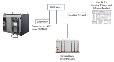
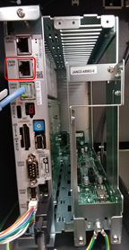
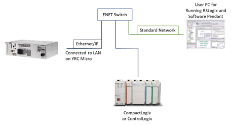
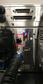
The basic network layouts for the YRC1000 and YRC1000micro are shown below. Basically, an Ethernet Switch should be used to put the PC, PLC, and Controller on the same network. For YRC1000, an Ethernet cable should be plugged into the port labelled “LAN2” inside the controller whereas for YRC1000micro an Ethernet cable should be plugged into the port labelled “LAN” on the outside of the controller.
| Network Layout (YRC1000) | Controller Port (YRC1000) |
 |
 |
| Network Layout (YRC1000micro) | Controller Port (YRC1000micro) |
 |
 |
Next, if the Controller IP Address is not on the same Network as the PLC, then it needs to be configured.
Configuring EtherNet/IP on Smart Pendant
This section describes how to define the size and mapping for the Ethernet/IP communications on the Controller. Using Smart Pendant, switch to Management security level and navigate to MENU->System Settings->I/O Configuration.
To communicate with a Rockwell PLC, the Controller must be configured as an Adapter. To create a new adapter, press the {NEW ALLOCATION} button on the top of the screen and select EtherNet/IP Adapter:
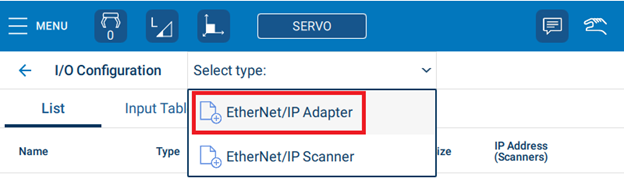
Note: only one Adapter can be configured for the Controller. If an Adapter is already present, you will need to edit its settings rather than create a new one.
After creating the Adapter, the Adapter Detail Settings screen will appear. The following settings can be configured from this screen:
- Input Size – input (i.e. PLC to Controller) in bytes. In the above example, 16 bytes are set (i.e. 16*8=128 individual input signals)
- Output Size – output (i.e. Controller to PLC) in bytes. In the above example, 16 bytes are set (i.e. 16*8=128 individual output signals)
- Input Instance – a unique ID for the Input (default is 50)
- Output Instance – a unique ID for the Output (default is 100)
- Configuration Instance – a unique IQ for the Configuration (default is 150)
- Input Starting Group – This will define where on the Smart Pendant Input map the Adapter will start.
- Output Starting Group – This will define where on the Smart Pendant Output map the Adapter will start.
Note: in general, there is no reason to change the Input/Output/Configuration Instance numbers. The only reason to change these would be if some other Ethernet/IP device in the network was using the same Instance ID number.
For this example, we will use the settings shown in the picture below. This configures the Adapter to have Input/Output sizes of 16 bytes (128 bits), and both will start at Group #17. This corresponds to I/O #s 129-256.
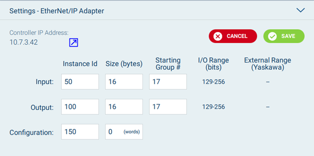
Press {SAVE} to finalize the configuration and then reboot the Controller for the changes to take effect.
Configuring the Rockwell PLC
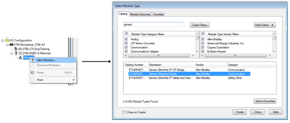
Next, the Ethernet/IP settings configured in the last section need to be mirrored on the PLC. To do this, first open the PLC Project File (.ACD). From the Controller Explorer, add a “Generic Ethernet Module” under the I/O Configuration:
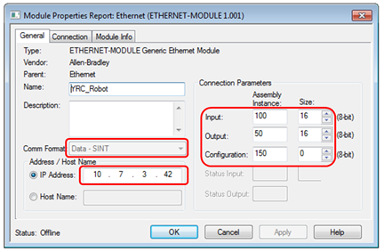
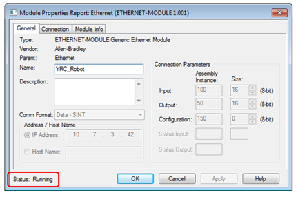
Next, double-click on this module to open the settings panel shown below. The following data should be set on this panel:
- Comm Format should be changed to “Data - SINT”. This will configure the data in 1 byte increments.
- Enter the IP Address of the Controller (e.g. “10.7.3.42” in this example)
- Enter the Instance Numbers and Sizes as entered before. One thing to note is that the Controller Input Instance should be mapped to the PLC Output Instance (and vice versa). This is shown in the table below as well.
|
Instance Type |
Controller ID# |
PLC ID# |
|
Input |
50 |
100 |
|
Output |
100 |
50 |
|
Configuration |
150 |
150 |
Next, download the PLC Program and turn the PLC to run mode.
While the PLC is running, open the Ethernet Module Settings and verify that the Status in the bottom left says “Running”. This will confirm that the basic communication is working.
Note: if the status is not set to “Running”, then there is something incorrect in the configuration. First, confirm that the Controller has been rebooted and is no longer in Maintenance Mode. Then, confirm that all Network Communications are still correct (i.e. both the Controller and PLC can be “pinged”). If that Status is still not “Running”, re-confirm the steps in the last two sections to debug the issue.
Verifying Communications using Smart Pendant
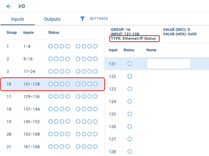
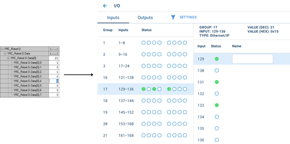
This section describes using Smart Pendant to verify the communication with the PLC. First, open the I/O Screen by pressing {MENU}, {Program/Operate}, and then {I/O}. The settings configured before should now display automatically on the Smart Pendant. For example, if the same settings from the example were used, then “Ethernet/IP Status” will automatically display in I/O Group 16 and “Ethernet/IP” will automatically display in I/O Group 17 as shown below.
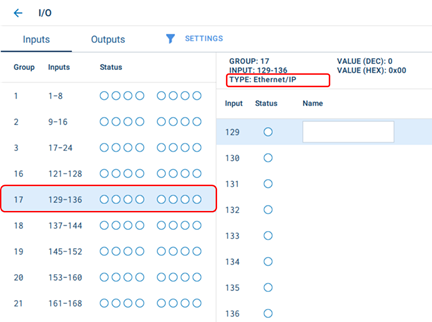
Now, turning on Output bits on the PLC should correspond to Input Signals on the Smart Pendant. For example, if we turn on the 1st, 3rd, and 5th bit from the PLC, the 1st, 3rd, and 5th Input Signals should turn on (Input #129, #131, #133) as shown below:
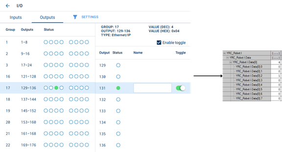
Similarly, toggling an Output from the Smart Pendant should turn on a bit on the PLC side. For example, toggling Output #131 (3rd mapped Output) should turn on the third bit of the data structure on the PLC:
It might be useful to test a few more I/O signals to verify that full range of mapped I/Os is behaving correctly.
Simple Handshaking Between PLC and Controller
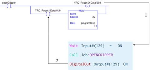
Now, simple handshaking can be performed between the PLC and Controller. For example, suppose the PLC needs to signal the Robot to open its gripper and then receive a signal back from the Robot when this action is complete. This could be done with the simple code below that contains two basic handshaking steps:
- When the “openGripper” variable is turned on, the PLC with latch the “YRC_Robot.O.Data[0].0” bit which corresponds to Input #129 on the Controller. Then, the Robot program can use the “Wait” instruction to wait for this signal and then run the “OPENGRIPPER” job.
- After the “OPENGRIPPER” job completes, the Robot program can turn on Output #129 with the “DigitalOut” instruction. This corresponds to the “YRC_Robot.I.Data[0].0” bit which can be checked to move the PLC ladder routine to the next step.
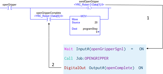
Note: using “aliases” in Logix Designer and I/O names on Smart Pendant could make this handshaking much easier to read as shown below.
Comments
0 comments
Please sign in to leave a comment.