Introduction
This document describes the configuration steps for the VIPA IM 053IP Ethernet I/P Remote I/O Block. NOTE: These instructions have been written for the 053-1IP00 module. The instructions for 053-1IP01 are different and covered in a separate document.
SLIO: Interface modules
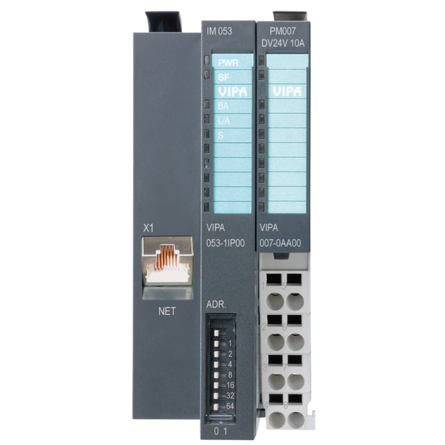
Interface modules (IM) form the interface between process level and parent bus system. All control signals are transmitted through the internal backplane bus to the electronics module (EM).
In the case of the interface module the bus interface and power module (PM) are integrated in a single casing. Both the bus interface and the electronics of the connected peripheral modules are supplied with power via the integrated power module.
Characteristics
|
 |
Configuration
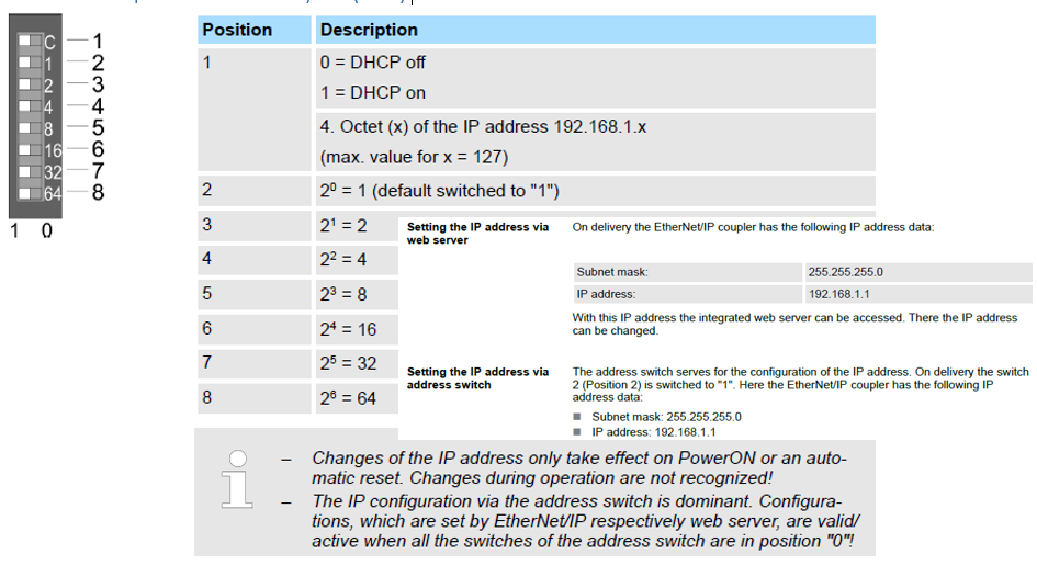
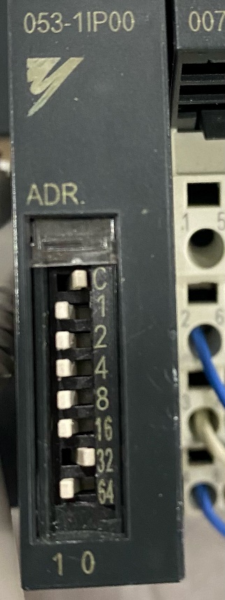
- Setting the IP address of the VIPA IM 053IP will need to be done via the dip switch settings that reside on the module. For this example, the IP Address is going to be 192.168.1.95
| 053-1IP00 Coupler DIP Switch Layout | 192.168.1.95 Dip Switch Settings |
 |
 |
- Configure a PC to be on the 192.168.1 subnet. Make sure the IP address used for the PC does not conflict with any other devices on network.
-
- Connect an Ethernet cable between your PC and the VIPA unit
- Open a web browser and enter address 192.168.1.95 If a web page does not load, ensure you can ping the VIPA unit, and no flashing red lights on the SF indicator are active.
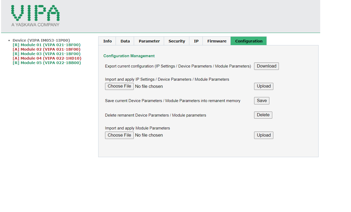
- Once the webpage has launched, you will need to configure the modules. This will need to be re-done if adding or removing any modules. Typically, the un-configured modules will be highlighted in red text.
-
- Select the configuration tab and delete remnant device parameters/module parameters
- Refresh the web page, you will now notice all the modules will be highlighted in green.
- Select on the configuration tab and save current device parameters/module parameters into memory.

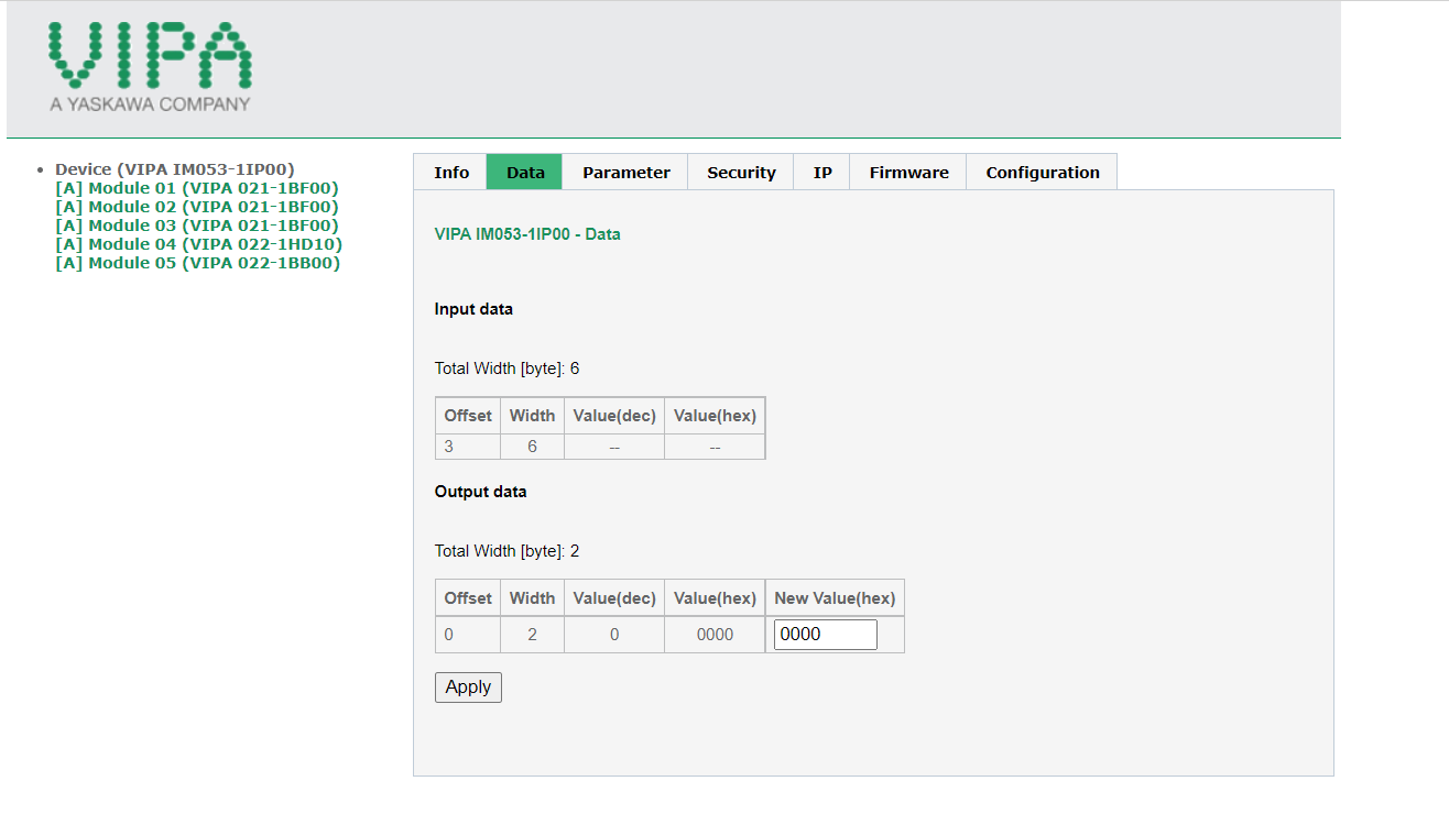
- After the modules have been configured. The byte size will need to be defined. Within each module the byte size will be located within the data tab. From the main module *Device (VIPA IM053-1IP00)* the data tab is going to have the total byte size for the Input/Output data.
-
- Note the offset data. This is defined by the assembly instance configuration.
- This data will take effect when setting up the robot controller.
- The example below is just for reference. Make sure to use the correct settings for your module when setting up the robot.
- The input and output instances of the VIPA module are a direct correlation to the robot settings unlike a PLC where they are mirrored.
- The configuration/assembly instance information will need to be configured within maintenance mode of the robot controller. The assembly instance information can be found within the VIPA 053-1IP00 manual under the Assembly Instances section.
-
- Hold the MAIN MENU key down on the pendant while powering the controller up to enter Maintenance Mode
- Login into SAFETY MODE Security
- Navigate through the following menus, SYSTEM>SETUP>OPTION FUNCTION>Ethernet/IP(CPU BOARD)>DEVICE INFORMATION list. Press SELECT to add a new device. Input the following parameters:
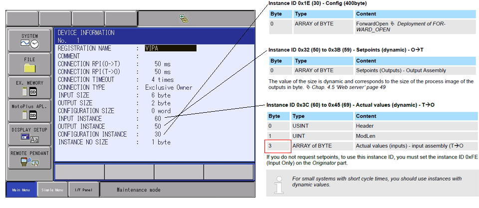
5.1 Within the detail screen of the Ethernet/IP(CPU Board) select SCANNER to add the VIPA Module in line 01.
-
- Register the IP address 192.168.1.95
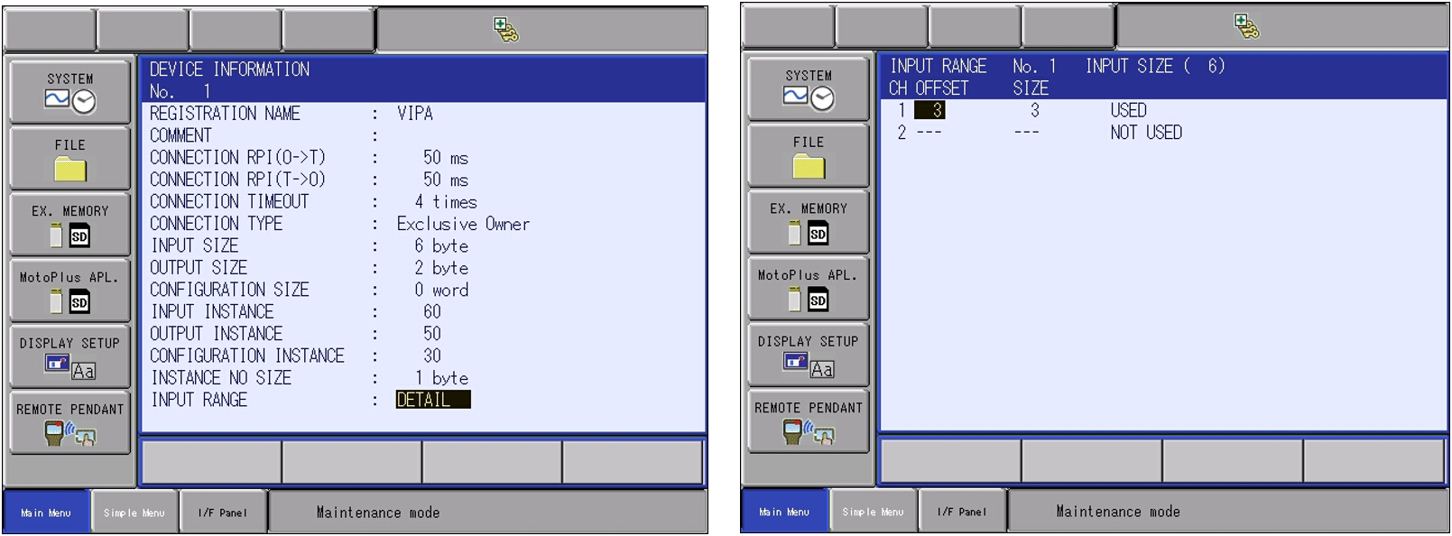
- Press SELECT on the VIPA device and select DETAIL. The device information will now be displayed.
- Press SELECT on the Input Range and define your offset. Once defined, press ENTER to register the device. *This is the offset data found from within the VIPA configuration page. See image above.* The offset will need to be implemented to compensate for the status bytes. This will allow the inputs and outputs to start using the same addressing.
- Press ENTER until you are back to the Ethernet/IP(CPU Board) Screen.
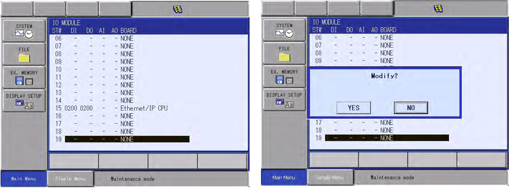
5.2 Once back at the Ethernet/IP (CPU board) settings, the next step will be Re-Configuration of the IO Module.
-
- Press ENTER twice You will notice the Ethernet/ IP CPU will now reflect the configuration.
- Press ENTER Once to allow for the Modify confirmation dialog box select “YES”
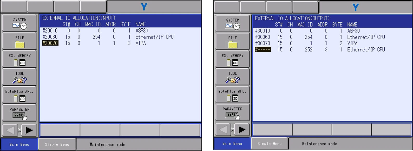
5.3 The VIPA module will need to be allocated within the controller I/O to ensure the device’s allocation.
-
- For this case the allocation mode will be set to manual. Highlight the detail text. Switch from auto to manual and press ENTER.
- From the input screen navigate to the VIPA module. Press SELECT and select INSERT if already inserted you will need to select MODIFY. Input the external starting address. These addresses correlate to the general purpose I/O if the ladder has modifications to the selected addressing the external to general I/O may not work. *ENSURE THE SELECT ADRESSING IS NOT BEING USED!*
- Ensure the byte size reflects the configuration. *If using the offset this will reflect the total byte size that was configured.*
- Press ENTER and repeat the above process for allocating the outputs.
- Once the allocation of the I/O is finished the VIPA unit is complete
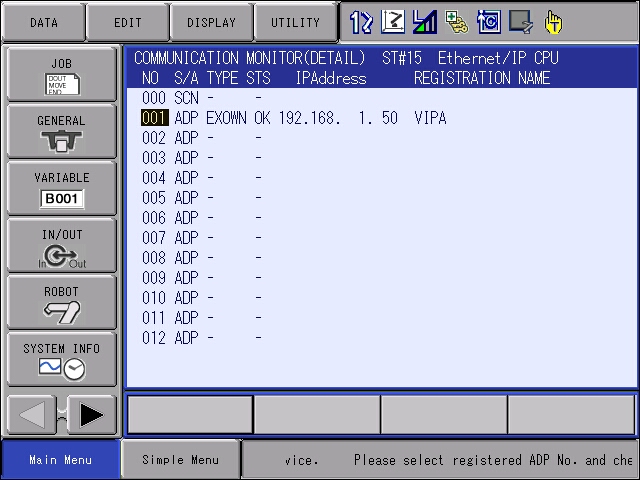
6. Verify the VIPA Module is communicating. Boot the controller into regular operation. This allows communications to be established to the VIPA module.
-
- Login into SAFETY MODE Security
- Navigate to the COMMUNICATION MONITOR tab. This can be found under the IN/OUT tab.
- Press SELECT on the Ethernet/IP CPU. The status of the VIPA module should say OK. If not OK, select the device for a detailed communication status with the adapter. Refer to the Ethernet/IP manual HW1483560 section 4.8 for the detailed alarm description here.
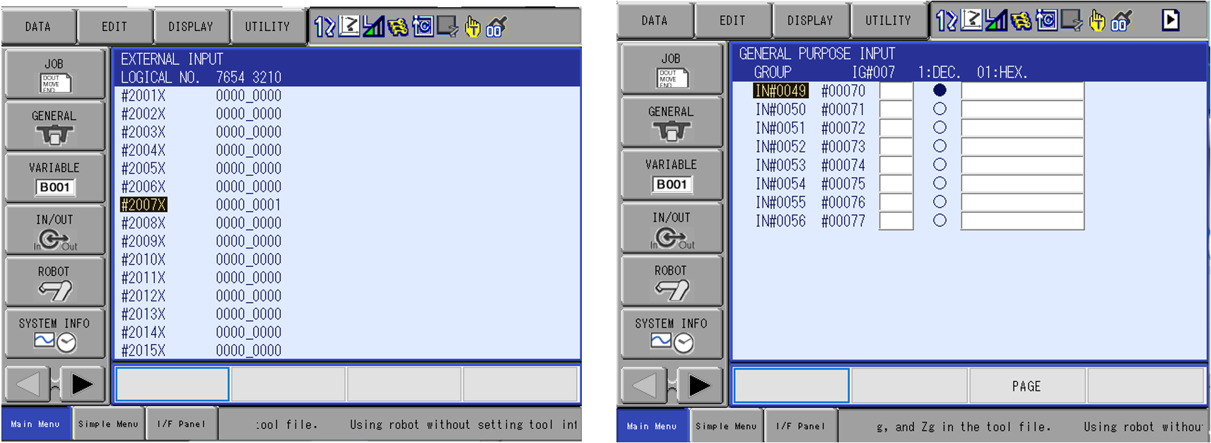
7. Test the Inputs from the VIPA module.
- Navigate to the EXTERNAL INPUT Screen and force the first input from the VIPA Module. External Input 20070 should be on.
- For this example, the YRC1000 Micro controller with an HC10 DT is being used. Navigate to the GENERAL PURPOSE INPUT screen. Verify the corresponding General Input 49 is on.
- If not working properly, ensure the device’s allocation addressing is correct within the robot’s concurrent IO.
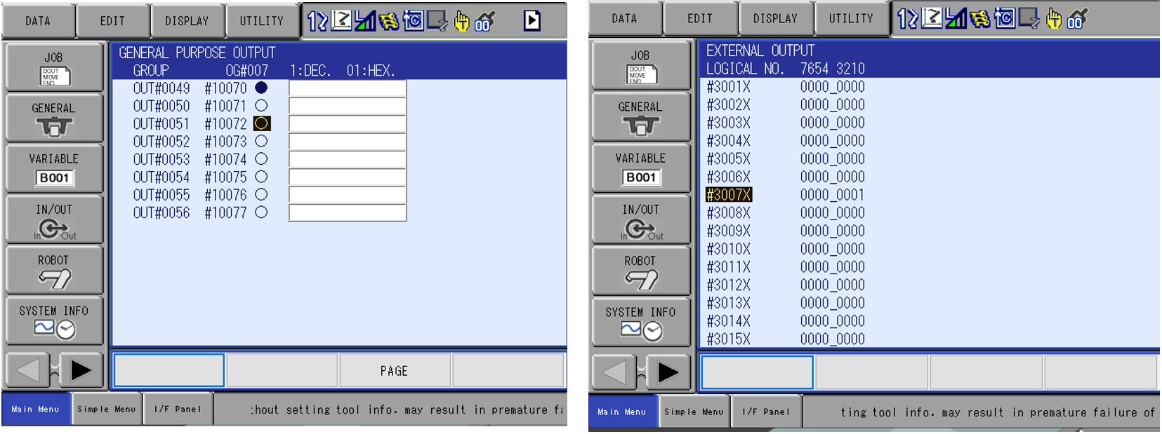
7.1 Test the outputs to the VIPA module.
-
- Navigate to the General Purpose Output Screen and force the first output to the VIPA module. This is GENERAL PURPOSE OUTPUT 49. To force the output on, use the INTERLOCK+SELECT keys while on the bullet.
- For this example, the YRC1000 Micro controller with an HC10 DT is being used. Navigate to the EXTERNAL OUTPUT Screen. The corresponding External Output is 30070. Verify this is on.
- If not working properly ensure the device’s allocation addressing is correct within the robots concurrent IO.
Comments
1 comment
This is a great informative article.
Please consider adding:
1) Setup of non 192.168.1.X IP addresses
2) Communication status on auxiliary address (7XXXX) for PLC/HMI display
3) Troubleshooting (Typical reasons why unit is not functional)
4) Modifying the setup (must be entirely deleted and re-added to scan list)
Please sign in to leave a comment.