INTRODUCTION
The following is a guideline on how a Yaskawa robot should be started from an external device such as a PLC. Similar logic would also apply to a manual push button control panel. Please remember that the exact sequence can vary and will reflect differences from programmer to programmer and application to application.
ADDITIONAL RESOURCES
Your Yaskawa robot features an internal concurrent I/O system (ladder logic) that maps all of the signals in use on your robot. Having a good understanding of the concurrent I/O can be beneficial for you. For even more information, please consult these articles:
| EXTERNAL DOCUMENT RESOURCES |
| DX100 Concurrent I/O instruction manual |
| DX200 Concurrent I/O instruction manual |
| YRC1000 Concurrent I/O instruction manual |
| YRC1000micro Concurrent I/O instruction manual |
| KNOWLEDGEBASE ARTICLES |
| Concurrent I/O Knowledgebase Support Article |
I/O MAP
Before moving forward, you should ensure you have the correct I/O map for your robot. The exact I/O map of your robot will vary. Factors contributing to the different I/O maps are as follows:
- Pendant application software. An arc welding robot will differentiate slightly when compared to a painting robot for the obvious reasons of signals related to the work that the robot is performing
- Hardware configuration. Most robots have 1 dedicated I/O card plus a fieldbus board such as Ethernet/IP. The exact configuration of your machine can and will influence your I/O map
- Country specific. Countries such as Canada will have a different I/O map associated to Ethernet/IP as compared to the United States. This is a localized country standard that has been in use for many generations of Yaskawa controllers.
In all cases, please consult your system documentation and/or your local Yaskawa tech support for help on identifying your current I/O map.
SIGNAL TYPES
 |
When the input signal is transitioning from a low state (e.g. 0) to a high state (e.g. 1) |
 |
When the input signal is maintained at a high state (e.g. 1) |
PRESTART CONSIDERATION
The teach pendant comes with a 3 position key switch. TEACH, PLAY and REMOTE. In order for the robot to accept signals from your PLC, it must be in the REMOTE position.
STARTUP SEQUENCE
| SIGNAL DESCRIPTION | SIGNAL TYPE |
CIO SIGNAL ADDRESS | |
| Remote mode confirmation | output | 70025 | |
| Play mode confirmation | output | 50054 | |
| Play mode selection | input | 40041 | |
| Servo power confirmation | output | 50073 | |
| Servo power selection | input | 40045 | |
| Master job confirmation | output | 50020 | |
| Master job selection | input | 40070 | |
| Start confirmation (operating) | output | 50070 | |
| External start | input | 40044 | |
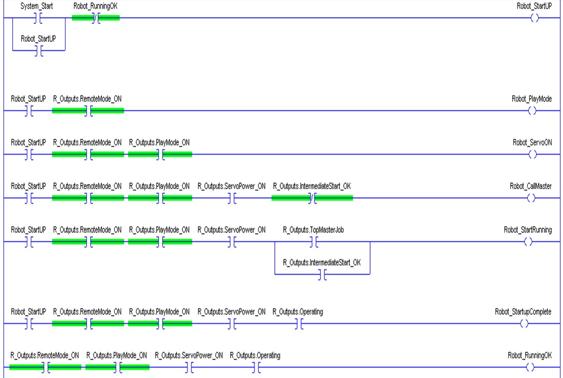
The robot only requires each signal be momentarily sent to activate the desired feature (servo’s, running, etc…) It does not need to be maintained and no harm will occur if you should do so. Best practice is to remove the signal once you have received confirmation.
In the example above, once the robot has been successfully started, all start-up logic is blocked from re-occurring.
Comments
1 comment
Excellent article! I have used it several times to resolve issues.
The ladder graphic is a bit blurry. Do you have a clearer version?
Ken
Please sign in to leave a comment.