In YAS 2.80 system software or later a set of “Safety CRC” monitoring bits was added. Complete details about this can be found in manual 178642-1CD by searching for these terms:
- CSCFG01, CSCFG02, CSCFG03, CSCFG04
- Yes, it says CSC…. But this series of bits relates to CRC. Maybe this is Japanese terminology or a translation error. In any case the bits / variables will be labeled as above even if they are not intuitive!
- For example:
- Pages 8-262 explains which Parameter Files and FSU DAT files control each bit above. The safety parameter and the data file for monitoring are shown below.
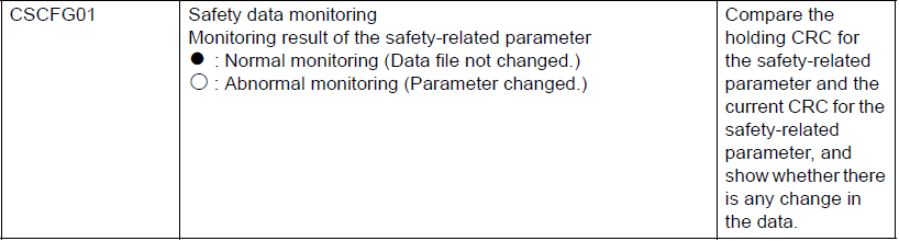
- CSCFG01 ~ Monitors these parameter groups / files:
- Robot alignment parameter (RC.PRM)
- Coordinate origin parameter (RO.PRM)
- Servo parameter (SV.PRM)
- Servo motor parameter (SVM.PRM)
- System definition parameter (SD.PRM)
- Motion function parameter (MF.PRM)
- Functional definition parameter (FD.PRM)
- Robot control extension parameter (RE.PRM)
- Safety function parameter (FMS.PRM)
- System alignment parameter (SC.PRM)
- CSCFG02 ~ Monitors the Safety Logic Circuit only:
- Safety logic circuit related file (YSFLOGIC.DAT)
- CSCFG03 ~ Monitors these safety related files and settings:
- Each axis motion range limited file (AXRNGLMT.DAT)
- Each axis speed monitoring file (AXSPDMON.DAT)
- Speed limited file (SPDLMT.DAT)
- Robot motion range limited file (RBRNGLMT.DAT)
- Tool angle monitoring setting file (TLANGMON.DAT)
- Tool change monitor/Tool number selection file (TLCHGMON.DAT)
- Home positioning file (ABSO.DAT)
- Tool file (TOOL.CND)
- Tool interference file (TOOLINTF.CND)
- CSCFG01 ~ Monitors these parameter groups / files:
- Section 8.26 of this manual (Safety Logic Circuit) shows how you can setup safety logic to send data out of the safety logic to an auxillary contact or possibly the safety network. Then receive a signal back from another source to indicate it is OK / Acceptable to continue. This uses the safety logic circuit signal “SICFGTRG”
A good practice would be to map these signals over the EtherNet/IP Safe network (or ProfiSAFE) to indicate something like “something critical has changed – can not start”. Interrogating exactly which bit changed we can determine if it was a motion/parameter related function, safety logic, or FSU related. This will then let staff determine which files to reload or require a higher level user to investigate why this changed. Generally you don’t want any user to just make changes and use the “CRC OK/Trigger” to clear the bits. An HMI screen that is permission locked could be added to quickly override this condition. But that decision and logic is left to end user to implement solutions as appropriate.
One thing to note about this feature is that the robot controller must have CRC Check Function set to Enable to use these signals appropriately. (This is not documented well.)
- Confirm the FSU board is set to used.
- In normal operation change to management mode or safety mode of security.
- Go to menu [SETUP] and select [FUNCTION ENABLE]
- Ensure that the "SAVE DATA CRC CHECK FUNC. (FSU)" is set to VALID.
Comments
0 comments
Please sign in to leave a comment.