Explicit messaging can be used to read/write variables from a Rockwell PLC. This offers another layer of hand-shaking between the Controller and PLC. This guide assumes that the basic communications between the Controller and PLC has already been established. This can be checked from the Ethernet Module Properties dialog while the PLC is online and running:
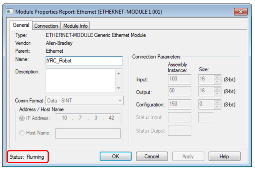
For more information on establishing communications between the Controller and PLC, see How do I configure communication with a Rockwell PLC?
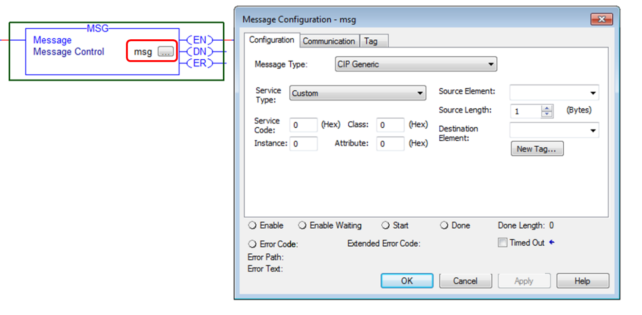
The basic procedure for reading/writing variables is to use the Rockwell “MSG” command to read/write between PLC variables and Controller Variables. The exact format of this command varies depending on the Variable type and whether you are reading or writing. The following sections will show the details of how to configure this instruction.
Reading/Writing Numerical Variables (B/I/D/R)
To read a numeric variable, first add a “MSG” command to the ladder and press the “…” button to bring up the Properties dialog.
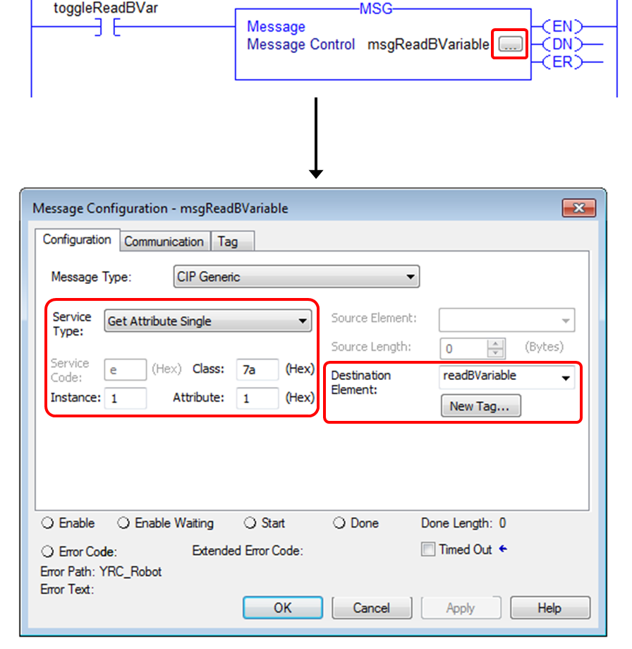
On the Configuration tab, the following information should be entered:
- Service Type: set to “Get Attribute Single”
- Service Code: will be automatically set to “e” for “Get Attribute Single”
- Class: set to desired Variable Type: 7a – Byte (B), 7b – Integer (I), 7c – Double (D), 7d – Real (R)
- Instance: variable number (e.g. 1 = B001, 15 = B015, etc.)
- Attribute: always set to 1
- Destination Element: PLC variable to store the Controller variable value. This must be set to the correct data type to match the Controller variable type (Byte (B) – SINT, Integer (I) – INT, Double (D) – DINT, Real (R) – REAL).
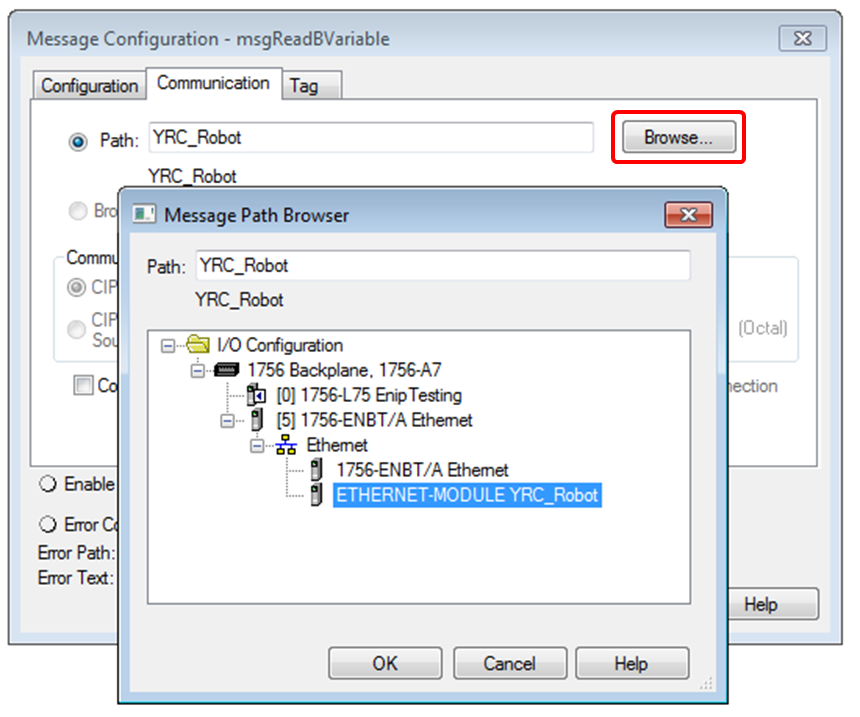
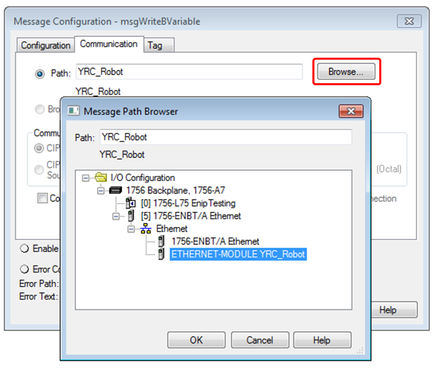
On the Communication tab, press the {BROWSE} button and navigate to the desired Ethernet Module.
Now, the instruction can be executed to retrieve the Controller Variable value and store it into the selected PLC Variable.
A similar process can be used to write PLC variables to the controller. First, insert a new “MSG” instruction for writing and press the “…” button to bring up the Properties dialog.
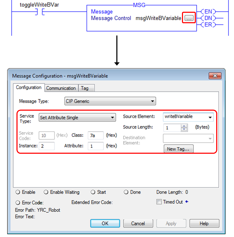
On the Configuration tab, the following information should be entered:
- Service Type: set to “Set Attribute Single”
- Service Code: will be automatically set to “10” for “Set Attribute Single”
- Class: set to desired Variable Type: 7a – Byte (B), 7b – Integer (I), 7c – Double (D), 7d – Real (R)
- Instance: variable number (e.g. 1 = B001, 15 = B015, etc.)
- Attribute: always set to 1
- Source Element: PLC variable to send to Controller. This must be set to the correct data type to match the Controller variable type (B – SINT, I – INT, D – DINT, R – REAL).
- Source Length: set to length in Bytes of Variable Type (B/SINT – 1, I/INT – 2, D/DINT – 4, R/REAL – 4)
Then, set the path to the correct Ethernet Module on the Communication tab.
Now, executing this instruction will write the value of the PLC Variable into the Controller Variable. The attached Logix Designer project (ENIP_ExplicitMsgExample.ACD) contains an example of reading and writing each Numeric Variable type.
The data entry is summarized in the following table:
|
YRC Controller Variable Type |
Rockwell Variable Type |
Variable Size |
Class Code |
|
Byte (B) |
SINT |
1 Byte |
0x7a |
|
Integer (I) |
INT |
2 Bytes |
0x7b |
|
Double (D) |
DINT |
4 Bytes |
0x7c |
|
Real (R) |
REAL |
4 Bytes |
0x7d |
Reading/Writing Position Variables
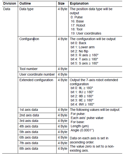
Position Variables are slightly more complicated as each Position Variable contains multiple values instead of just a single value. The format for the Position Variable structure is 13 4-byte integers (DINT in Logix Designer) shown below:
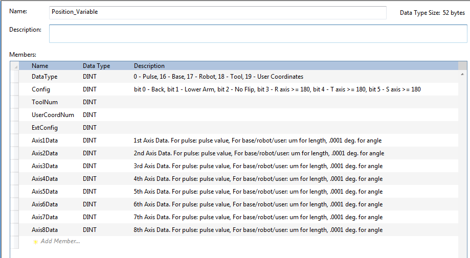
For convenience, it is useful to create a custom UDT (User-Defined Type) in Logix Designer. An example of this is included in the attached project file (ENIP_ExplicitMsgExample.ACD ) as well as an exported version of this UDT (Position_Variable.L5X).
Next, add a new “MSG” instruction and click the “…” to bring up the Property dialog.
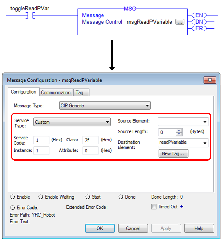
On the Configuration tab, the following information should be entered:
- Service Type: set to “Custom”
- Service Code: set to 1
- Class: set to 7f for Position Variable
- Instance: variable number (e.g. 1 = P001, 15 = P015, etc.)
- Attribute: set to 0
- Destination Element: PLC Variable to hold the Position Variable data. If using the example code, the “Position_Variable” UDT can be used for this – otherwise, it must match the structure described before.
- Source Length: set to 0
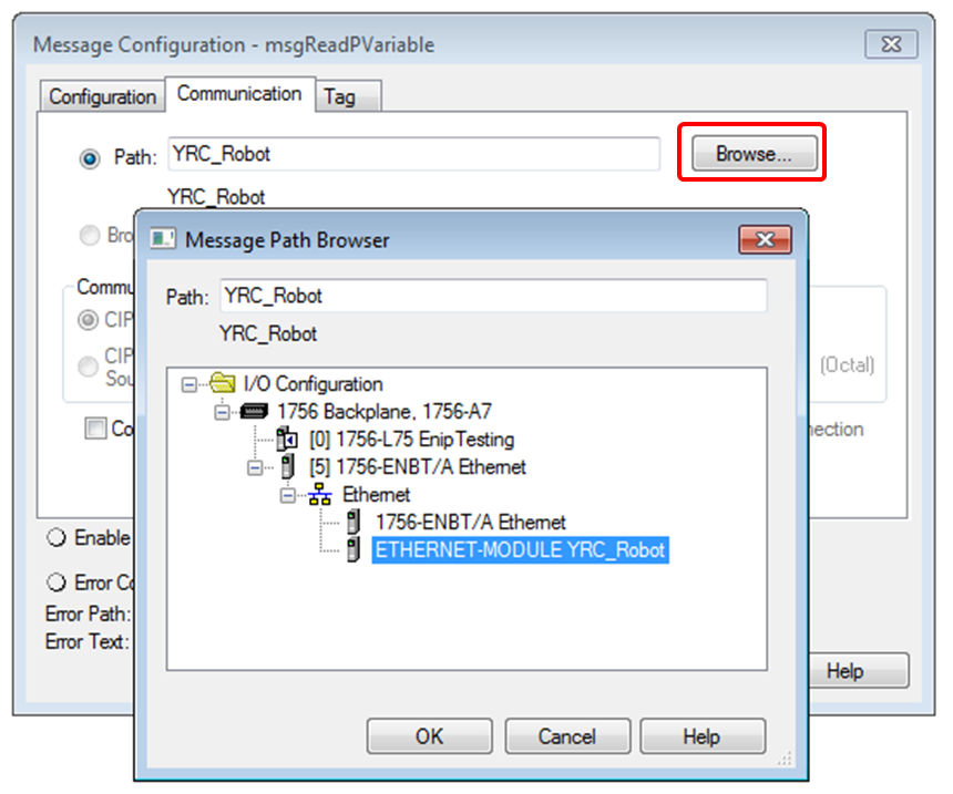
Then, set the path to the correct Ethernet Module on the Communication tab.
A similar process can be used to write Position Variables to the controller. First, insert a new “MSG” instruction for writing and press the “…” button to bring up the Properties dialog.
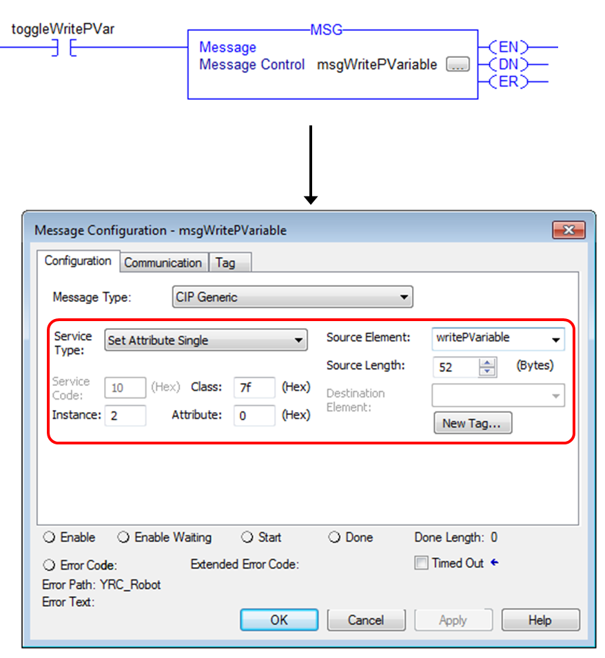
On the Configuration tab, the following information should be entered:
- Service Type: set to “Set Attribute Single”
- Service Code: will be automatically set to “10” for “Set Attribute Single”
- Class: set to 7f for Position Variable
- Instance: variable number (e.g. 1 = P001, 15 = P015, etc.)
- Attribute: set to 0
- Source Element: PLC variable to send to Controller. If using attached example, the “Position_Variable” UDT can be used here.
- Source Length: 52 bytes (13 * 4 Byte DINT)
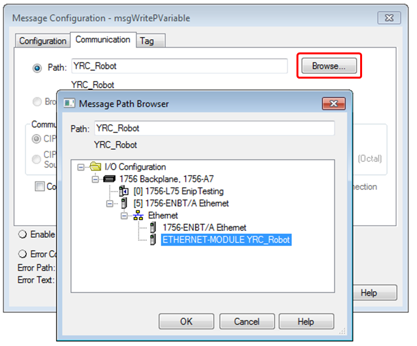
Then, set the path to the correct Ethernet Module on the Communication tab.
The attached project file (ENIP_ExplicitMsgExample.ACD) contains an example of reading and writing a Position Variable.
Comments
0 comments
Please sign in to leave a comment.